Wind motor vane propeller-changing device

A wind turbine, blade pitch technology, applied in wind turbine, wind turbine control, engine and other directions, can solve the problems of meshing impact, vibration, affecting the life of gear pairs, etc.

Inactive Publication Date: 2009-05-06
上海驰风机电科技有限公司
View PDF0 Cites 19 Cited by
  • Summary
  • Abstract
  • Description
  • Claims
  • Application Information

AI Technical Summary

Problems solved by technology

For such a pitch change device, on the one hand, due to the gap between the gear meshes, it is easy to cause meshing impact, generate vibration, and...

Method used


Image

  • Wind motor vane propeller-changing device
  • Wind motor vane propeller-changing device
  • Wind motor vane propeller-changing device

Examples


no. 1 example

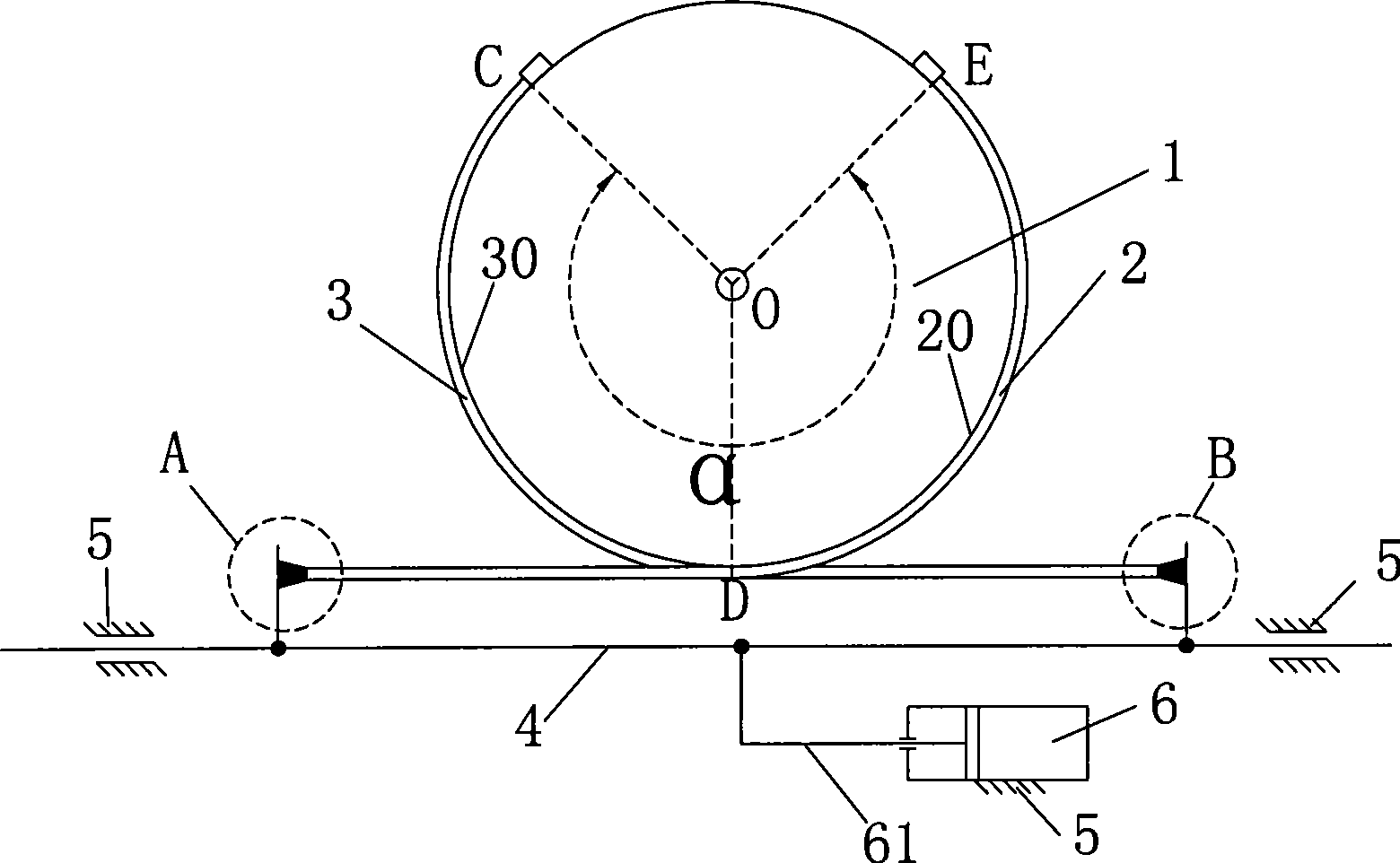
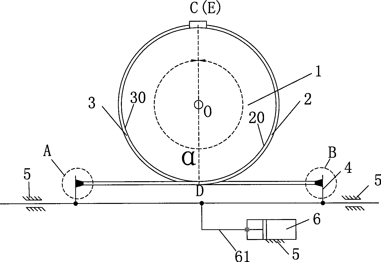
[0028] Such as figure 1 As shown, the pitch control device of this embodiment includes a linear drive device 6 and a transmission device. The blade root 1 is cylindrical and is rotatably arranged on the hub 5 through a pitch bearing (not shown in the figure). The linear drive device 6 The power output member 61 moves linearly. The transmission device includes a push-pull rod 4 having a first connection end A and a second connection end B. The transmission device also includes a first flexible member 2 and a second flexible member 3 . Wherein, one end of the first flexible member 2 is connected with the first connecting end A of the push-pull rod, and the other end is connected with the blade root 1 through the connector E, and a part of the first flexible member 2 is covered on the first connecting end A of the blade root 1. On one side 20, the first connecting end A of the push-pull rod 4 is driven by the first flexible member 2 to rotate forwardly to realize the pitch change...

no. 2 example

[0035] Such as figure 2 and 2 As shown in a, the pitch control device of this embodiment includes a linear drive device 62 and three transmission devices, a coupling frame 72 and a spring 97, each transmission device correspondingly drives a blade, and the blade is rotatably arranged through a pitch bearing 82 On the hub 52, the power output member 621 of the driving device 62 moves linearly. The transmission device of this embodiment is the same as the transmission device of the first embodiment and the connection method with the blade root 12 is also the same, but most basically, each The transmission device includes a linearly movable push-pull rod 42, a first flexible member 22 and a second flexible member 32; wherein, the linearly movable push-pull rod 42 has a first connection end A2 and a second connection end B2; the first One end of the flexible member 22 is connected to the first connection end A2 of the push-pull rod, and the other end is connected to the blade ro...

no. 3 example

[0039] Also refer to image 3 , Figure 3a and figure 1 , the difference between this embodiment and the first embodiment is that the end of the flexible member is connected with a tension adjusting device, image 3 or Figure 3a The tension adjuster shown is available for figure 1 The first connecting end A and the second connecting end B of the middle push-pull rod 4 .

[0040] Wherein, numerals 23a and 23b indicate flexible parts, numeral 10a indicates screws, numerals 43a and 43b indicate baffles, numeral 91 indicates adjusting nuts, numeral 90 indicates lock nuts, numeral 92 indicates washers, and numeral 10b indicates connecting rods.

[0041] as attached image 3 As shown, the tension adjusting device of this embodiment includes a screw 10 a , an adjusting nut 91 , and a lock nut 90 . The flexible part 23a passes through the central hole of the screw 10a and is fixed at the end of the screw 10a. The baffle plate 43a connected with the push-pull rod has a hole and ...


PUM


Abstract

The invention provides a variable propeller device for a wind motor blade, which comprises a drive unit and a transmission gear which drives the blade to rotate, wherein the drive unit such as a hydraulic cylinder or a feed screw nut can generate linear propulsion to drive a push-and-pull rod in the transmission gear to perform linear movement; the push-and-pull rod drives a first flexible element and a second flexible element which are coated on the tail of the blade; and the first flexible element and the second flexible element drive the blade to rotate, so as to realize variable propeller. When the number of the blades of a wind motor is more than two, a linkage frame can be arranged between the drive unit and the push-and-pull rod of the transmission gear, and drives the transmission gear to perform linear movement, so as to realize synchronous variable propeller of various blades.

Description

technical field [0001] The invention relates to a wind power engine blade pitch changing device. Background technique [0002] In large-scale wind turbines, each blade not only revolves around a common axis, but also rotates around its own axis. , by making the blade rotate to reduce the angle of attack, reduce the aerodynamic force and then reduce the speed until it stalls), this kind of self-rotation motion is called pitch or pitch adjustment, and the device that can realize pitch is called variable pitch in this paper. Paddle device. [0003] The existing pitch device mainly adopts electric pitch: the blade is installed on the hub through the pitch bearing, so the blade can rotate relative to the hub around its own axis, the bearing ring connected to the blade by the pitch bearing is provided with an internal gear, and the motor passes through the variable speed The box drives the pinion gear meshed with the internal gear to rotate to drive the blades to rotate to achie...

Claims


Application Information

Patent Timeline
IPC IPC(8): F03D7/04
CPCY02E10/723Y02E10/72
Inventor 周宏孝任超张志明
Owner 上海驰风机电科技有限公司
Why Eureka
Try Eureka