Light guide board

A light guide plate and light source technology, applied in the field of light guide plates, can solve the problems of poor pass rate of light guide plates, time-consuming and costly processing, etc., and achieve the effect of improving the pass rate of processing and reducing processing costs

Active Publication Date: 2009-05-06
AU OPTRONICS CORP
View PDF0 Cites 5 Cited by
  • Summary
  • Abstract
  • Description
  • Claims
  • Application Information

AI Technical Summary

Problems solved by technology

The above-mentioned problems have caused the poor pass rate of the light guide plate, and the problem of time-consuming and costly processing

Method used


Image

  • Light guide board
  • Light guide board
  • Light guide board

Examples


Embodiment Construction

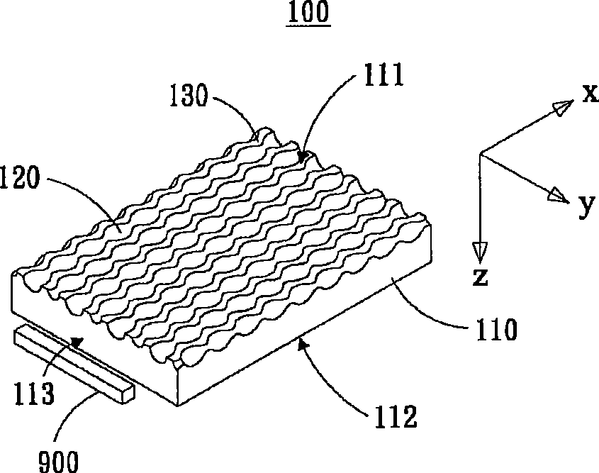
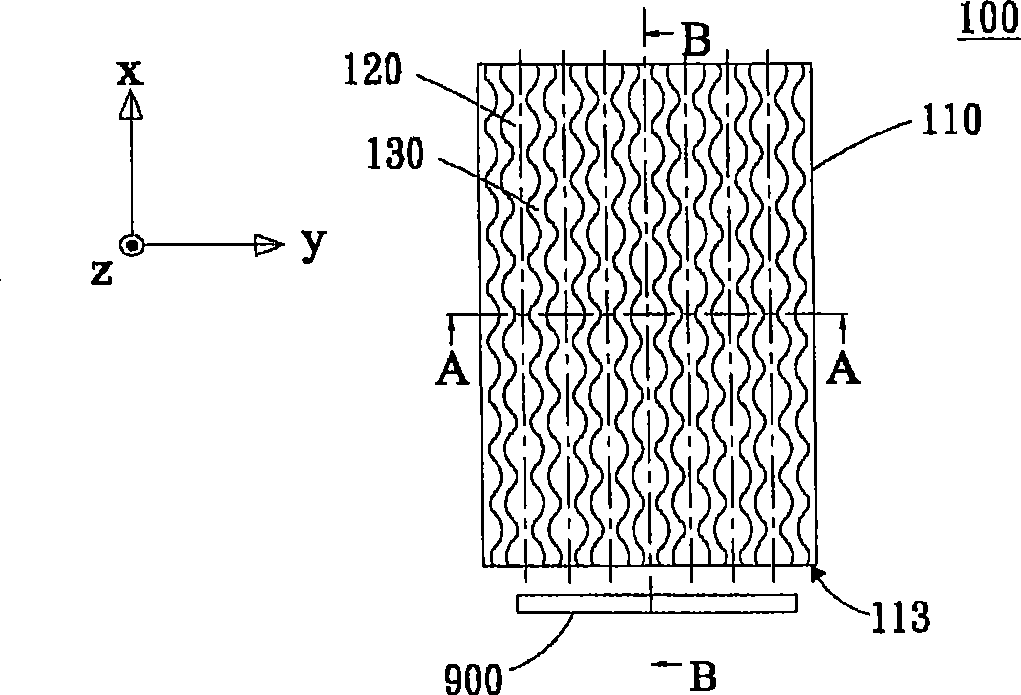
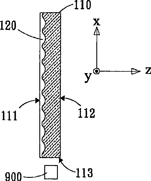
[0032] see figure 1 and figure 2 As shown, a light guide plate 100 disclosed in the first embodiment of the present invention is used to guide the light of a light source, change the direction of the light, and make the light uniformly pass through a liquid crystal panel. The light guide plate 100 includes a transparent layer 110 and a plurality of micro grooves 120 formed on the transparent layer 110 .

[0033] see again figure 1 , figure 2 , image 3 and Figure 4 As shown, the light-transmitting layer 110 has a light incident surface 113, a first plane 111 and a second plane 112, the first plane 111 and the second plane 112 are respectively connected to two opposite sides of the light incident surface 113, and The first plane 111 is opposite to the second plane 112 . Wherein, the light source 900 is disposed on one side of the light-incident surface 113 , so that light enters the light-transmitting layer 110 through the light-incident surface. The light is uniforml...


PUM


Abstract

The invention discloses a light guide plate for guiding luminous beams of a light source, which comprises a photic zone and a plurality of microgrooves. The photic zone is provided with a light incident surface, a first plane, and a second plane, wherein the light source is arranged on one side of the light incident surface, and the first plane is connected with the light incident surface and opposite to the second plane; and the microgrooves are arranged on the first plane, and every microgroove extends along an extending direction respectively, wherein a vertical distance from an edge of every microgroove to the extending direction of every microgroove shows a first sine wave form along the extending direction, and depth changes at the bottom of every microgroove show a second sine wave form along the extending direction. The microgrooves with continuous changes are used for refracting the luminous beams of the light source, thereby the luminous beams leave uniformly from the first plane, and simultaneously defects or flaws caused by bug dusts are avoided. Therefore, the light guide plate does not need high processing precision to be manufactured, and reduces processing cost and promotes process percent of pass.

Description

technical field [0001] The invention relates to a light guide plate applied to a backlight module, in particular to a light guide plate which can improve the qualified rate and reduce the production cost. Background technique [0002] The liquid crystal panel needs light to penetrate the liquid crystal layer, and the human eye can observe the changes of the liquid crystal layer. Existing liquid crystal panels use a backlight module to project light from the back side of the liquid crystal layer. The light provided by the backlight module must penetrate the liquid crystal layer evenly, and the light projected to the liquid crystal layer must have uniform brightness. However, the light source type is a tubular light source, such as a cold cathode tube, and the light emitted by the tubular light source cannot be projected on a plane uniformly and with uniform brightness. Therefore, the optical structure of the backlight module must enable the light to penetrate the liquid crys...

Claims


Application Information

Patent Timeline
Patent Type & Authority Applications(China)
IPC IPC(8): F21V8/00G02B6/00G02F1/13357G02F1/1335
Inventor 邹明智曾兆弘邓琮圣
Owner AU OPTRONICS CORP
Why Eureka
Try Eureka