Integrated apparatus used for fuel cell humidifying

A fuel cell and integrated technology, applied in the direction of fuel cells, fuel cell additives, solid electrolyte fuel cells, etc., can solve the problems of low humidification efficiency, large pressure loss, large humidification stack volume, etc., and achieve humidification efficiency High, increased humidification capacity, small footprint effect

Active Publication Date: 2009-05-06
SHANGHAI MUNICIPAL ELECTRIC POWER CO +1
View PDF0 Cites 11 Cited by
  • Summary
  • Abstract
  • Description
  • Claims
  • Application Information

AI Technical Summary

Problems solved by technology

[0017] However, the design of the above-mentioned humidifying device can only be suitable for the condition of relatively high pressure operation of the fuel cell. When the operating pressure is high, a single external humidifying device can easily reach the relative humidity required for the operation of the fuel cell. The amount of water taken away is much larger than when the operating pressure is high, and it is difficult for a single external humidification device to achieve the relative humidity required for fuel cell operation. If the length and width of the above humidification device are increased to meet the humidification requirements, the volume of the humidification stack Very large, the pressure loss is also large, and the humidification efficiency is very low

Method used


Image

  • Integrated apparatus used for fuel cell humidifying
  • Integrated apparatus used for fuel cell humidifying
  • Integrated apparatus used for fuel cell humidifying

Examples


Embodiment 1

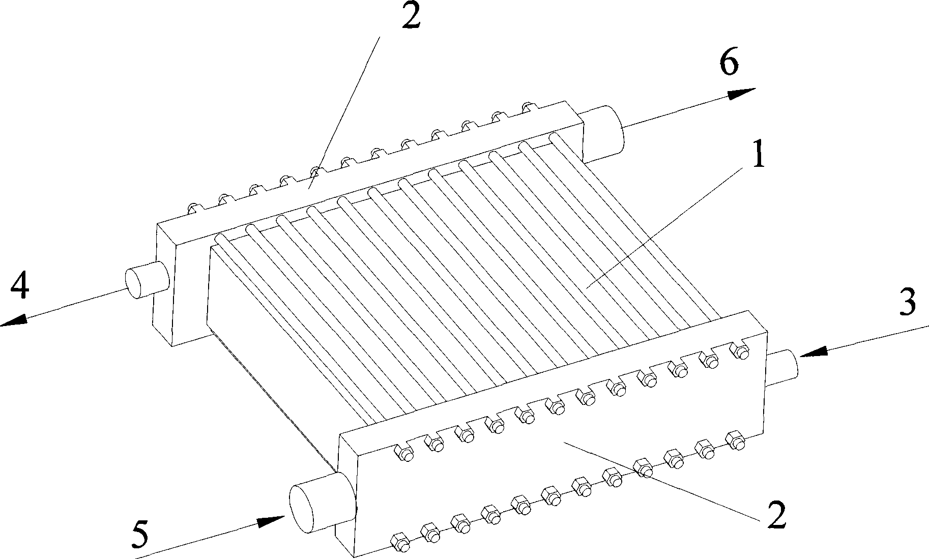
[0036] like figure 2 As shown, an integrated external humidification device for fuel cell cars has a length of 500mm, a width of 150mm, and a height of 200mm. Collector plate 7, terminal end plate 2a, 2b, described humidification pile 1 comprises 20 deflectors, 40 diaphragms, the deflectors and diaphragms are 40mm long and 10mm wide, and the diaphragms are water-permeable Air film, a diaphragm is interposed between the deflector and the deflector to form a humidification unit, and the humidification unit is stacked up and down to form a humidification part, and the air humidification stack 1a is formed by the air deflector , Diaphragm and cooling water deflector are stacked in sequence. Air deflectors are provided with air deflectors on both sides of the air deflector, and cooling water deflectors are provided on both sides of the cooling water deflector. Air inlet and outlet holes and cooling water inlet and outlet holes are arranged on the flow plate and the cooling water ...

Embodiment 2

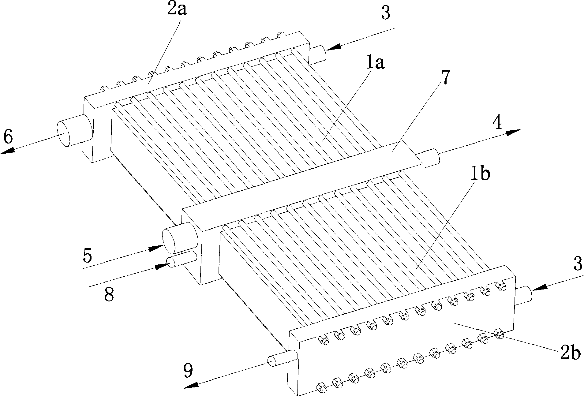
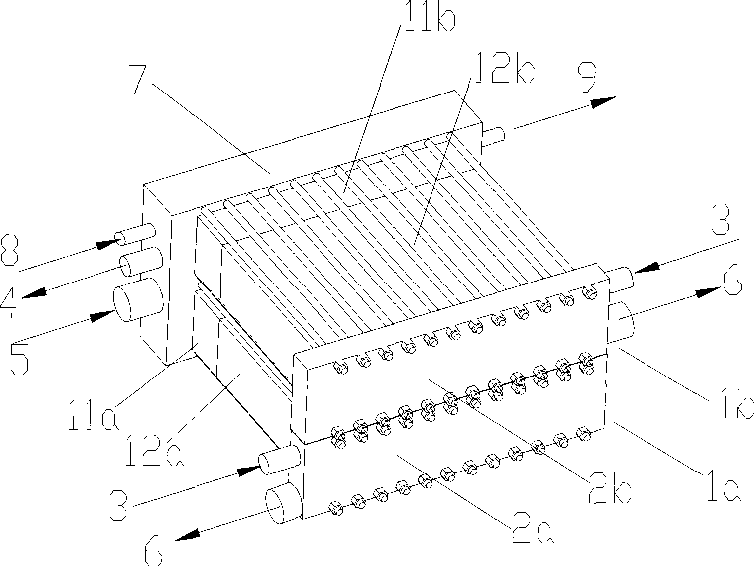
[0039] like image 3 As shown, an integrated external humidification device for a fuel cell forklift is 300mm long, 250mm wide, and 250mm high. , the humidification stacks 1a and 1b are respectively arranged at the upper and lower positions on the same side of the central collector plate 7, the humidification stack 1a includes a hydrogen humidification part 11a and an air humidification part 12a, and the hydrogen humidification part 11a is close to the central collector plate 7. The air humidifying part 12a is close to the terminal end plate 2a; the humidifying stack 1b includes a hydrogen humidifying part 11b and an air humidifying part 12b, the hydrogen humidifying part 11b is close to the central collector plate 7, and the air humidifying part 12b is close to the terminal end plate 2b, after the air flows in from the air inlet pipe 5 on the central collector plate 7, it flows into the two humidifying stacks 1a, 1b at the upper and lower positions respectively, passes throug...

Embodiment 3

[0042] like Figure 4 As shown, an integrated external humidification device for a fuel cell bus, the device includes four sets of humidification stacks 1a, 1b, 1c, 1d, a central collector plate 7, end end plates 2a, 2b, 2c, 2d, The four groups of humidifying stacks 1a, 1b, 1c, and 1d are respectively arranged at the front, rear, left, and right ends of the central collector plate 7, wherein the humidifying stacks 1a are all composed of hydrogen humidification parts, and the humidifying stacks 1b, 1c are all composed of air humidification The humidification stack 1d is composed of a hydrogen humidification part 11d and an air humidification part 12d, the hydrogen humidification part 11d is close to the end end plate 2d, and the air humidification part 12d is close to the central collector plate 7.

[0043] Air flows in from the air inlet pipes 5 on the terminal end plates 2b, 2c, 2d of the humidification stacks 1b, 1c, 1d, and flows out from the air outlet pipes 6 on the centr...


PUM


Abstract

The invention relates to an integrated device used for humidifying a fuel cell, which comprises humidifying reactors, a central flow plate and tail end plates. The humidifying reactors comprise a plurality of guide plates and a plurality of diaphragms, wherein each diaphragm adopts a pervious and air isolating diaphragm, a diaphragm is arranged between any two guide plates to form a humidifying unit, the humidifying units are longitudinally overlapped to form a humidifying part, the quantity of the humidifying reactors is at least two, the two groups of humidifying reactors are arranged on both sides of the central flow plate or the front part and the rear part, the left part and the right part, or the upper part and the lower part of one side of the central flow plate, a tail end plate is arranged at the other end of each group of humidifying reactor opposite to the central flow plate, the end plated, the at least two groups of humidifying reactors and the central flow plate are integrally installed, air, hydrogen gas and cooling water respectively enter into the humidifying reactors from the end plates of the central flow plate or each humidifying reactor, and then flow out of the humidifying reactors from the end plate of each humidifying reactor or the central flow plate. Compared with the prior art, the integrated device has the advantages that the flow resistance can be reduced, the integrated device is suitable for low pressure operation, the humidifying effect can be significantly enhanced, and the like.

Description

technical field [0001] The invention relates to a fuel cell, in particular to an integration method of a proton exchange membrane fuel cell with an internal humidifying device. Background technique [0002] An electrochemical fuel cell is a device that converts hydrogen fuel and oxidant into electrical energy and reaction products. The internal core component of the device is the membrane electrode (Membrane Electrode Assembly, referred to as MEA). The membrane electrode (MEA) is composed of a proton exchange membrane and two porous conductive materials, such as carbon paper, sandwiched between the two sides of the membrane. On the two boundary surfaces of the membrane and the carbon paper, there are even and finely dispersed catalysts for initiating electrochemical reactions, such as metal platinum catalysts. Conductive objects can be used on both sides of the membrane electrode to draw the electrons generated during the electrochemical reaction through an external circuit...

Claims


Application Information

Patent Timeline
Patent Type & Authority Applications(China)
IPC IPC(8): H01M8/04H01M8/10H01M8/04119H01M8/1007
CPCY02E60/521Y02E60/50
Inventor 胡里清章波
Owner SHANGHAI MUNICIPAL ELECTRIC POWER CO
Why Eureka
Try Eureka