Device and method for cooling large-heat-flux device by using magnetic field and impressed current

A technology of heat flux density and applied current, applied in electrical components, structural parts of electrical equipment, cooling/ventilation/heating renovation, etc., can solve the problems of no automatic adjustment ability, pressure pump occupying space, pressure pump noise, etc. To achieve the effect of novel driving mode, good cooling effect and improving flow speed

Pending Publication Date: 2022-01-07
UNIVERSITY OF CHINESE ACADEMY OF SCIENCES
View PDF0 Cites 0 Cited by
  • Summary
  • Abstract
  • Description
  • Claims
  • Application Information

AI Technical Summary

Problems solved by technology

[0007] In view of the above situation, in order to overcome the defects of the prior art, the present invention provides a device and method for cooling devices with high heat flux density by using a magnetic field and an applied current, which effectively solves the problem of cooling devices with a high heat flux density by using a magnetic field in the current market. The device and method require the pressure pump to be actively driven, the pressure pump occupies a certain space, is limited by the space, has a small heat dissipation area, and the pressure pump will generate noise during operation, and does not have the ability to automatically adjust the thermal power of the device with a large heat flux density. The problem of high flow resistance

Method used


Image

  • Device and method for cooling large-heat-flux device by using magnetic field and impressed current

Examples


Embodiment 1

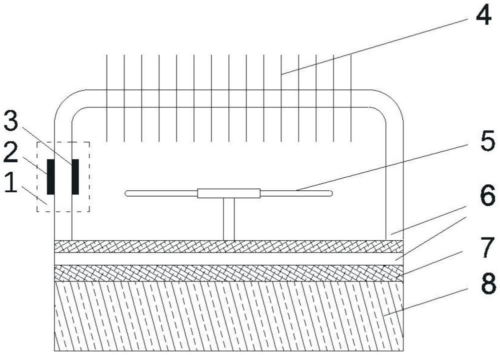
[0028] Embodiment one, by figure 1 Given, the present invention includes a heating device 8, a thermally conductive material 7 is installed on the top of the heating device 8, a conductive fluid circuit 6 is provided inside the thermally conductive material 7, and a first electrode material 2 and a second electrode are provided at the left end of the conductive fluid circuit 6 The material 3 and the magnetic field coverage area 1, the other end of the conductive fluid circuit 6 is provided with a fin structure 4 installed outside the circuit, the top of the heat conduction material 7 is installed with a cooling fan 5, and the fin structure 4 is made of aluminum alloy, copper or alloy The sheet-type heat dissipation structure made of copper, and the heat dissipation fan 5 is a forced convection heat dissipation structure driven by electricity.

Embodiment 2

[0029] Embodiment 2. On the basis of Embodiment 1, the material of the thermally conductive material 7 is a copper block. By changing the structure of the thermally conductive material 7, it can transfer heat from the heat generating device 8 more efficiently.

Embodiment 3

[0030] Embodiment three, on the basis of embodiment one, the conductive fluid circuit 6 includes conductive fluid and liquid metal or conductive fluid and conductive metal powder, through the setting of the conductive fluid circuit 6, the conductive fluid flowing in it such as gallium, gallium alloy, mercury , potassium-sodium alloy, salt solution or conductive metal powder can enhance the heat transfer effect very well.


PUM


Abstract

The invention belongs to the technical field of large-heat-flux device cooling, and discloses a device and method for cooling a large-heat-flux device by using a magnetic field and impressed current. The device comprises a heating device, red copper with good heat-conducting property is mounted at the top of the heating device, and a conductive fluid loop is arranged in the red copper metal. As an active heat dissipation technology, compared with a traditional passive heat dissipation technology which utilizes extension structures such as fins to enhance natural convection to achieve cooling, the device and method can flexibly adjust heat dissipation power by adjusting the magnetic field or impressed current, and the device and method have enhanced heat dissipation effect and a larger application range, and can be applied to application occasions with high heat power and large heat flux density; compared with a driving mode such as a pressure pump and the like, the mode of driving the fluid through the magnetic field and the current effect cannot generate noise, the flowing state is stable, additional flowing resistance cannot be increased; and no additional mechanical moving part is arranged, so that the device is simple in structureandeasy to install and maintain.

Description

technical field [0001] The invention belongs to the technical field of cooling high heat flux devices, and specifically relates to a device and method for cooling high heat flux devices by using a magnetic field and an applied current. Background technique [0002] The heat dissipation problem of high power and high heat flux devices is closely related to engineering practice. The traditional small heat dissipation power technology has been developed and mature. This invention intends to propose a solution for applications with high heat flux density and high heat dissipation requirements. As an active heat dissipation technology, the present invention uses Lorentz force to drive fluid movement, liquid metal flows into the heat exchanger to bring heat to the external environment, and adopts a well-developed fin extension structure to enhance the performance of the heat exchanger. Fans and other forced heat dissipation devices are used for cooling, and then the reflow enters ...

Claims


Application Information

Patent Timeline
Patent Type & Authority Applications(China)
IPC IPC(8): H05K7/20
CPCH05K7/20136H05K7/20272
Inventor 王增辉陈昭奇倪明玖
Owner UNIVERSITY OF CHINESE ACADEMY OF SCIENCES
Why Eureka
Try Eureka