
Ultrasonic straight line motor and automatic focusing/zooming system driven thereby

A linear motor and auto-focusing technology, applied in generator/motor, camera focusing device, projector focusing device, etc., can solve problems such as quick start and stop response, imaging error, etc.

Inactive Publication Date: 2009-05-06
BOLY MEDIA COMM SHENZHEN
View PDF2 Cites 40 Cited by
  • Summary
  • Abstract
  • Description
  • Claims
  • Application Information

AI Technical Summary

Problems solved by technology

[0005] 3. Quick start and stop response, response time in milliseconds
The advantage of this system is that the structure is very simple, and the existing optical lens is directly used to form the rotor, with few parts, low cost, and high control precision. However, for some optical equipment, the rotation of the lens during focusing or zooming There will be a certain degree of imaging error

Method used


Image

  • Ultrasonic straight line motor and automatic focusing/zooming system driven thereby
  • Ultrasonic straight line motor and automatic focusing/zooming system driven thereby
  • Ultrasonic straight line motor and automatic focusing/zooming system driven thereby

Examples


Embodiment 1

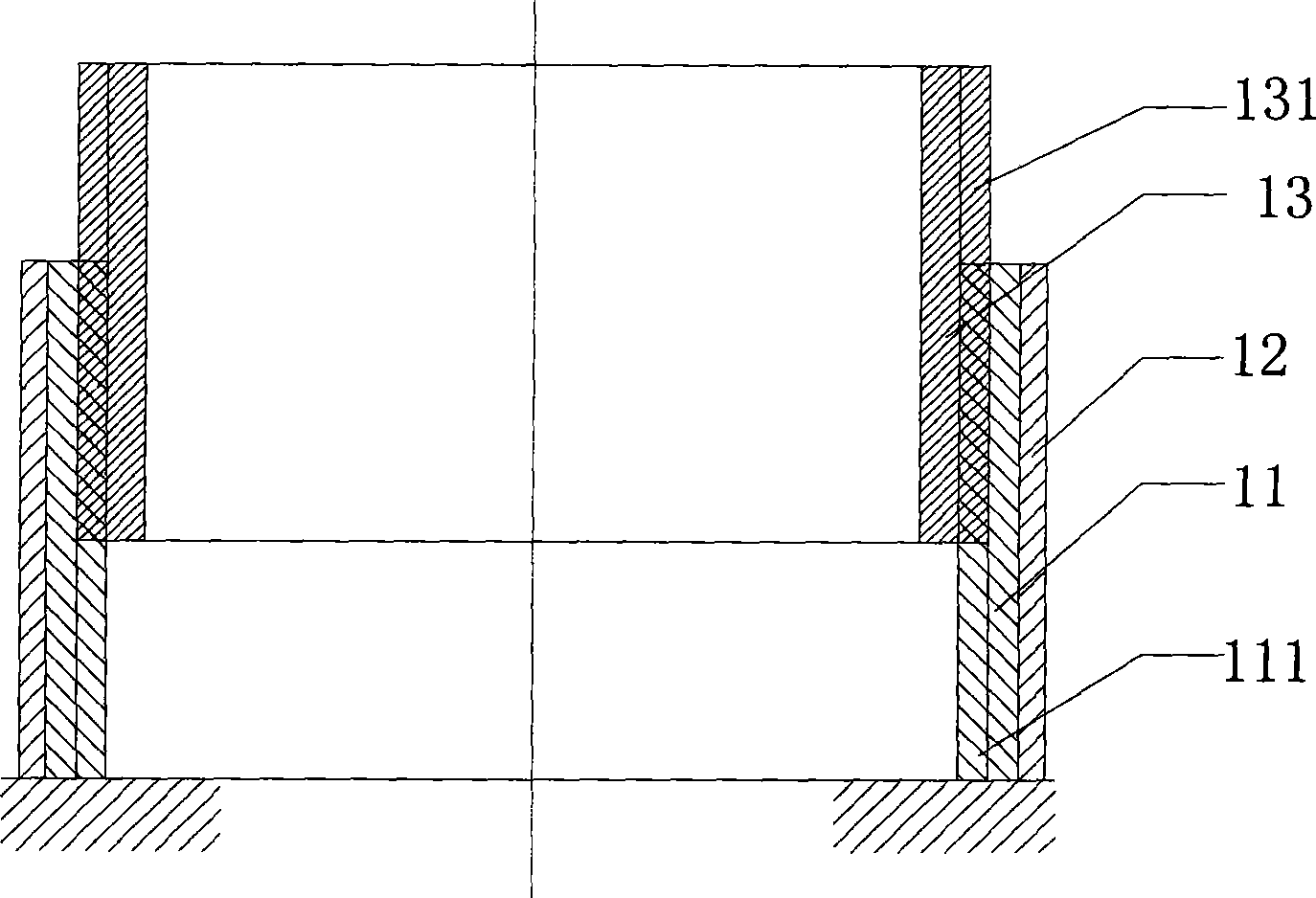
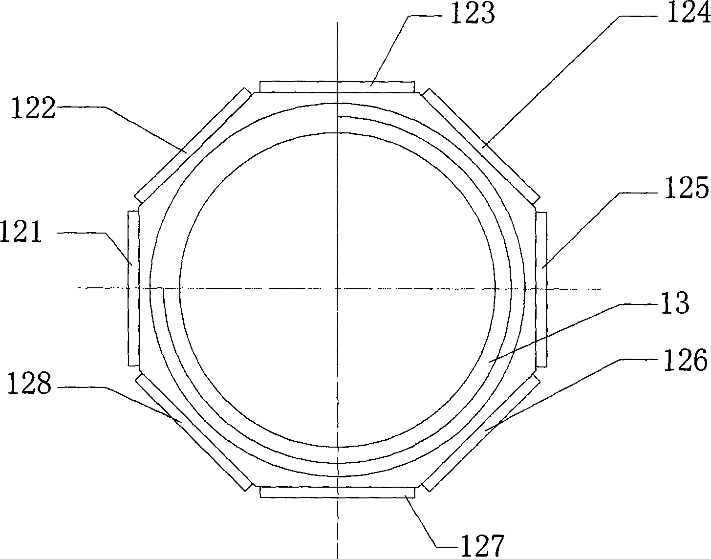
[0045] It is an octahedral ultrasonic linear motor driven by two-stage threads, and its basic structure is as follows: Figure 3a and Figure 3b As shown, it consists of an outer cylinder stator, a middle cylinder rotor, an inner cylinder and a guide mechanism.

[0046] The base 31 of the outer cylinder stator is a hollow barrel-shaped regular octahedron of metal material, and its inner wall is processed with threads 311; the outer surface of the stator base 31 is fixed with a piezoelectric sheet 32, and in this embodiment, the piezoelectric sheet 32 ​​includes eight The piezoelectric sheets 321-328, the piezoelectric sheets 321-328 will generate the required mechanical vibration traveling waves after being excited.

[0047] Usually, the piezoelectric plates on the polyhedral stator are sequentially fed with two-phase orthogonal voltages, that is, the voltages whose phases are sinωt and cosωt respectively. Each piezoelectric sheet vibrates correspondingly after being excited...

Embodiment 2

[0054] Example 2 is a variant of Example 1. The difference between it and the above-mentioned Embodiment 1 is that the guide rod 35 integrates a column 351 for shape retention, such as Figure 4a and Figure 4b As shown, the column 351 fixed on the stator and the guide rod 35 are integrally formed. The cross section of the column 351 is a right triangle, and the cross section of the guide rod 351 is an arc shape. The middle of the hypotenuse of the triangle protrudes. The guide rod 35 with a circular arc cross section is embedded in the chute 341, and the two right-angled surfaces of the column 351 are respectively on the same plane as the adjacent piezoelectric sheet, so that the two columns located at the outer corners of the octahedral motor 351 (also can be four) expands the external shape of whole motor to more regular tetrahedron, and this column 351 also can play the effect of keeping shape to the corner part of octagonal motor, is more conducive to picking up and ins...

Embodiment 3

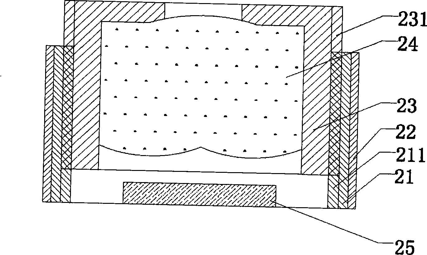
[0056] Embodiment 3 On the basis of Embodiment 1, an optical lens and a photosensitive chip are added to form an AF Lens Module. Such as Figure 5a and Figure 5b As shown, a group of optical lenses 443 are embedded in the inner tube 44 for collecting external visual signals. At the same time, on the plane perpendicular to the optical axis of the optical lens 443 at the center of the bottom of the motor, a photosensitive chip 471 is fixed to convert the optical signal collected from the lens group into an electrical signal to provide material for further image processing.

[0057]A square cavity is provided at the bottom of the stator base 46 for accommodating a photosensitive chip 471 . In the embodiment, the photosensitive chip 471 is firstly fixed on a flexible circuit board (FPC) 47 , and the flexible circuit board 47 is then fixed on the bottom frame of the stator base 46 . The other end of the flexible circuit board 47 has a circuit interface 472 external to the photo...


PUM


Abstract

The invention discloses an ultrasonic linear motor which comprises an outer tube stator, a middle tube rotor, an inner tube, a guide mechanism and a piezoelectric piece, wherein the piezoelectric piece is fixed on the outer side surface of the stator, the stator drives the middle tube rotor to rotate, the inner tube is connected with the stator through the guide mechanism, and the middle tube rotor drives the inner tube to make linear motion. The invention also discloses an automatic focusing / zooming system driven by the ultrasonic linear motor, an optical lens is inserted inside the inner tube, and a light sensing chip is fixed on a plane at the bottom part of the stator. The invention has the advantages that two-stage drive motor structure is provided, the helical motion generated by the rotor in the first-stage drive is restored to be the only linear motion of the inner tube through the second-stage drive, only the linear displacement without rotation is generated during the working process of the automatic focusing / zooming lens module, so as to meet the requirements of high pixel, and high-precision automatic focusing or zooming, and the invention still has simple and compact structure, is suitable for the miniaturization, and has high precision of the linear displacement.

Description

technical field [0001] The invention relates to a motor structure and an autofocus / zoom lens system, in particular to a thread-driven polyhedron thin-walled ring type ultrasonic linear motor and the structural design of an autofocus / zoom lens module using the motor. Background technique [0002] The piezoelectric ultrasonic motor is a driving mechanism made of a specific structure using the inverse piezoelectric effect of piezoelectric materials. It is generally composed of functional components such as piezoelectric ceramics, stators, rotors, and pre-pressure mechanisms. Some motors may also have transmission mechanism. The traveling-wave piezoelectric ultrasonic motor uses piezoelectric materials to generate mechanical vibration traveling waves of ultrasonic frequency on the surface of the stator, and drives the rotor to rotate by means of the friction between the stator and the rotor. It has the following characteristics superior to ordinary electromagnetic motors: [0...

Claims


Application Information

Patent Timeline
IPC IPC(8): H02N2/04G03B13/34
Inventor 李毅张明俊胡笑平
Owner BOLY MEDIA COMM SHENZHEN
Learn More