Camera based six degree-of-freedom target measuring and target tracking device with rotatable mirror

A mirror, camera technology, used in measuring devices, re-radiation of electromagnetic waves, radio wave measurement systems, etc., can solve the problems of inaccurate, expensive, and time-consuming repositioning procedures for measuring radial distances

Inactive Publication Date: 2009-05-06
FARO TECH INC
View PDF5 Cites 51 Cited by
  • Summary
  • Abstract
  • Description
  • Claims
  • Application Information

AI Technical Summary

Problems solved by technology

As a result, the camera system is limited in its ability to view narrow openings
The field of view of the camera system is also limited, which means a time-consuming repositioning procedure is required to view all targets in the measurement space
[0010]Systems consisting of only a single camera are cheap to manufacture, but are less accurate in measuring radial distances when using small targets suitable for robotic control or factory automation
Adding a rangefinder improves accuracy but is too expensive for most robotics and factory automation applications

Method used


Image

  • Camera based six degree-of-freedom target measuring and target tracking device with rotatable mirror
  • Camera based six degree-of-freedom target measuring and target tracking device with rotatable mirror
  • Camera based six degree-of-freedom target measuring and target tracking device with rotatable mirror

Examples


Embodiment Construction

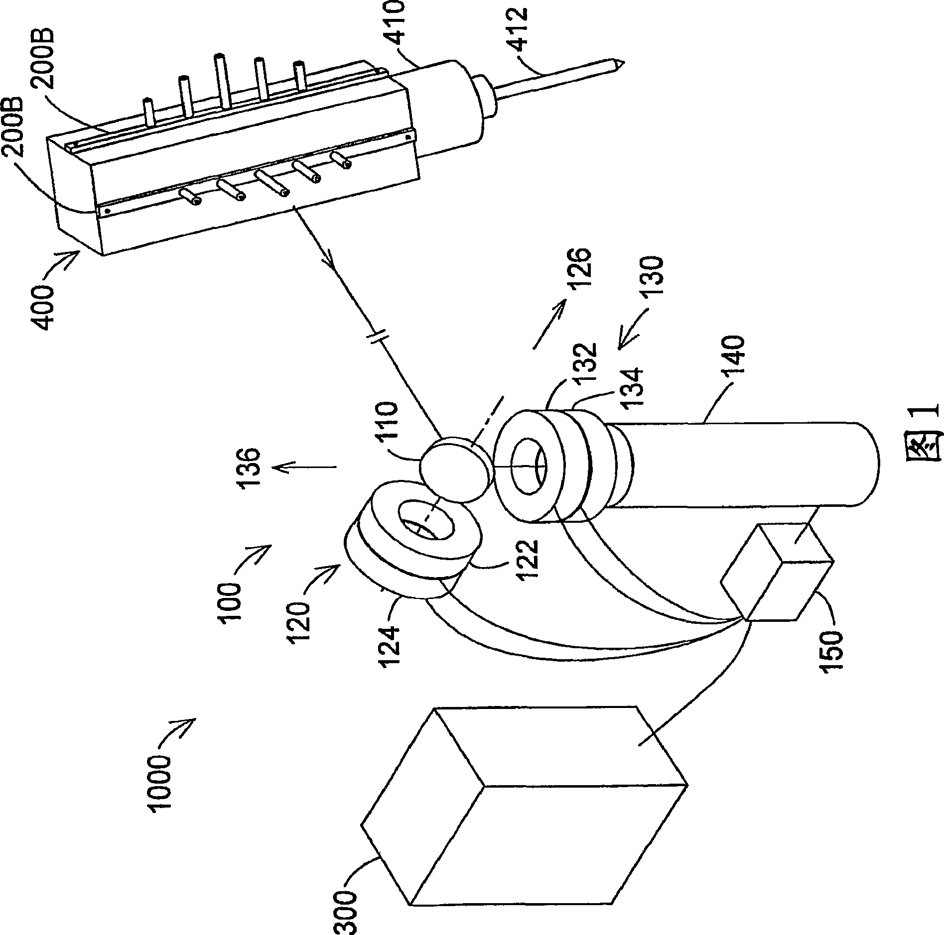
[0028] As shown in FIG. 1 , an exemplary six-degree-of-freedom (6-DOF) tracker 1000 may include a tracking camera arrangement 100 , a target 400 and a computer 300 . Six degrees of freedom may be, for example, x, y, z coordinates of target 400 as well as pitch, roll, and yaw.

[0029] The entire tracking camera device 100 may include a mirror 110 , a first angle component 120 , a second angle component 130 , a camera 140 and a processor 150 .

[0030] The first angle assembly 120 includes a first angle shaft (not shown) on which a goniometer 122 and a motor 124 are mounted. The goniometer 122 is preferably an angle encoder and the motor 124 is preferably a servo motor. A first angular axis (not shown) rotates about a first axis 126, which in this figure is the zenith axis. The first and second axes intersect at a point in space known as the gimbal node.

[0031] The second angle assembly 130 includes a second angle shaft (not shown) on which a goniometer 132 and a motor 134...


PUM


Abstract

An embodiment may comprise a camera based target coordinate measuring system or apparatus for use in measuring the position of objects in manner that preserves a high level of accuracy. This high level of measurement accuracy is usually only associated with more expensive laser based devices. Many different arrangements are possible. Other embodiments may comprise related methods of using a camera based target coordinate measuring method for use in measuring the position of objects. Many variations on the methods are possible. For example, a camera based coordinate measuring system for use in measuring the position of a target relative to at least one frame of reference without requiring use of a laser range finder for measuring distance may comprise at least three or more light sources located on a target wherein the light sources are located on the target at known three-dimensional coordinates relative to each other; at least one rotatable mirror rotatable on about a first axis and a second axis; a camera located to receive light emitted by the light sources that is reflected off the mirror; two angular measuring devices to measure the angles of rotation of the mirror about the first and second axes; and a processor for determining up to three positional degrees of freedom and up to three rotational degrees of freedom of the target.

Description

[0001] cross reference [0002] This application claims priority to US Provisional Application 60 / 793,811, filed April 21, 2006, which is hereby incorporated by reference in its entirety. Background technique [0003] The present disclosure relates to coordinate measuring equipment. A coordinate measuring device is a class of instruments that measure the three-dimensional coordinates of a point by sending a laser beam at that point. The laser beam may impinge directly on the point or may impinge on a retro-reflector target in contact with the point. In either case, the instrument determines the coordinates of the point by measuring the distance and two angles relative to the target. Distances are measured with distance measuring devices such as absolute range finders or interferometers. Measure the angle with an angle measuring device such as an angle encoder. A gimbaled beam steering mechanism within the instrument directs the laser beam to the point of interest. Exempla...

Claims


Application Information

Patent Timeline
Patent Type & Authority Applications(China)
IPC IPC(8): G01S17/42G01S5/16
CPCG01S5/163G01B11/002
Inventor 罗伯特·E·布里奇斯
Owner FARO TECH INC
Why Eureka
Try Eureka