Electric power steering device
A technology of electric power steering and steering system, which is applied in the direction of electric steering mechanism, automatic steering control components, steering mechanism, etc., and can solve problems such as burnout
- Summary
- Abstract
- Description
- Claims
- Application Information
AI Technical Summary
Problems solved by technology
Method used
Image
Examples
no. 1 approach 》
[0064] A first embodiment of the present invention will be described with reference to FIGS. 1 to 9A-C.
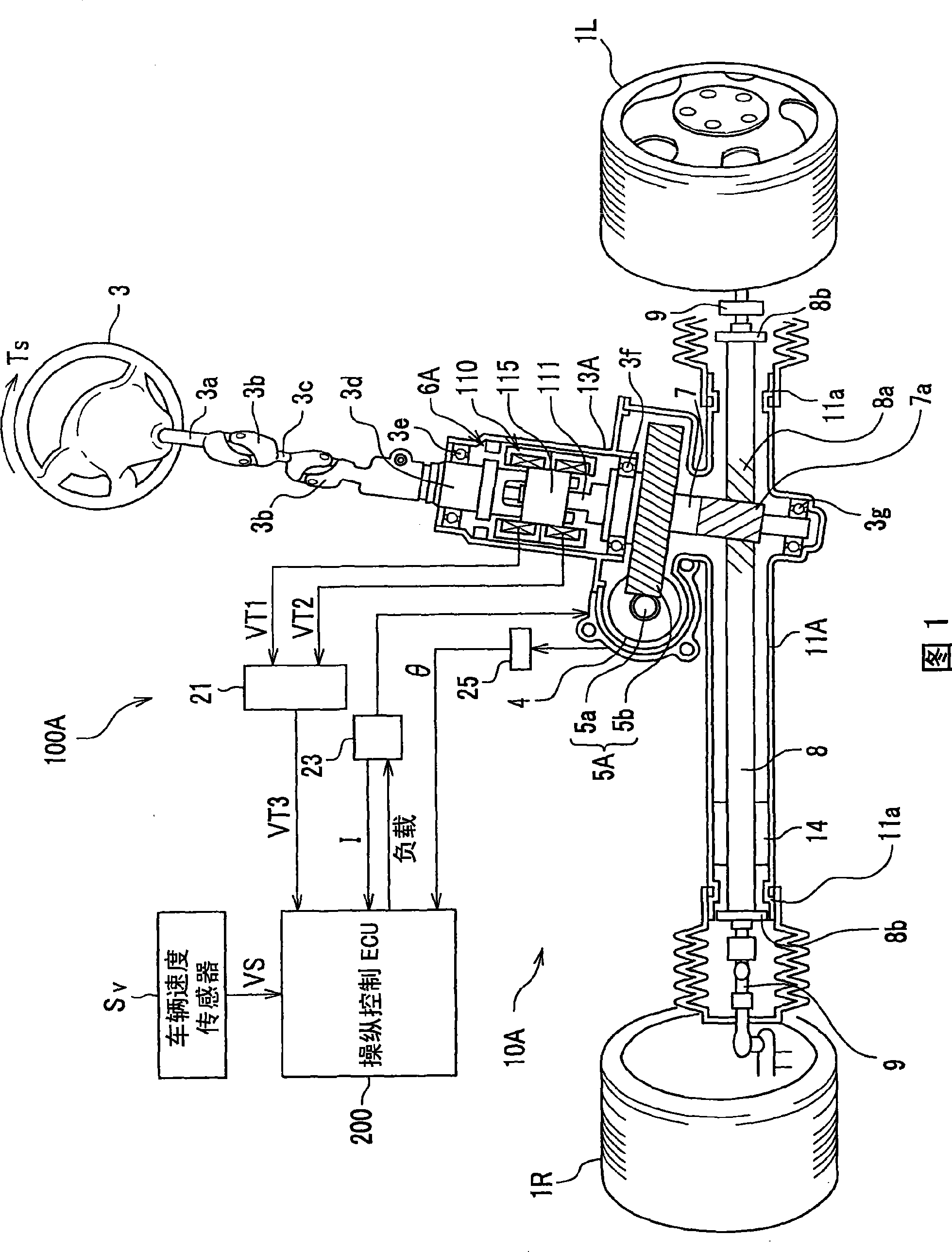
[0065] FIG. 1 is a configuration diagram of an electric power steering system according to a first embodiment of the present invention.
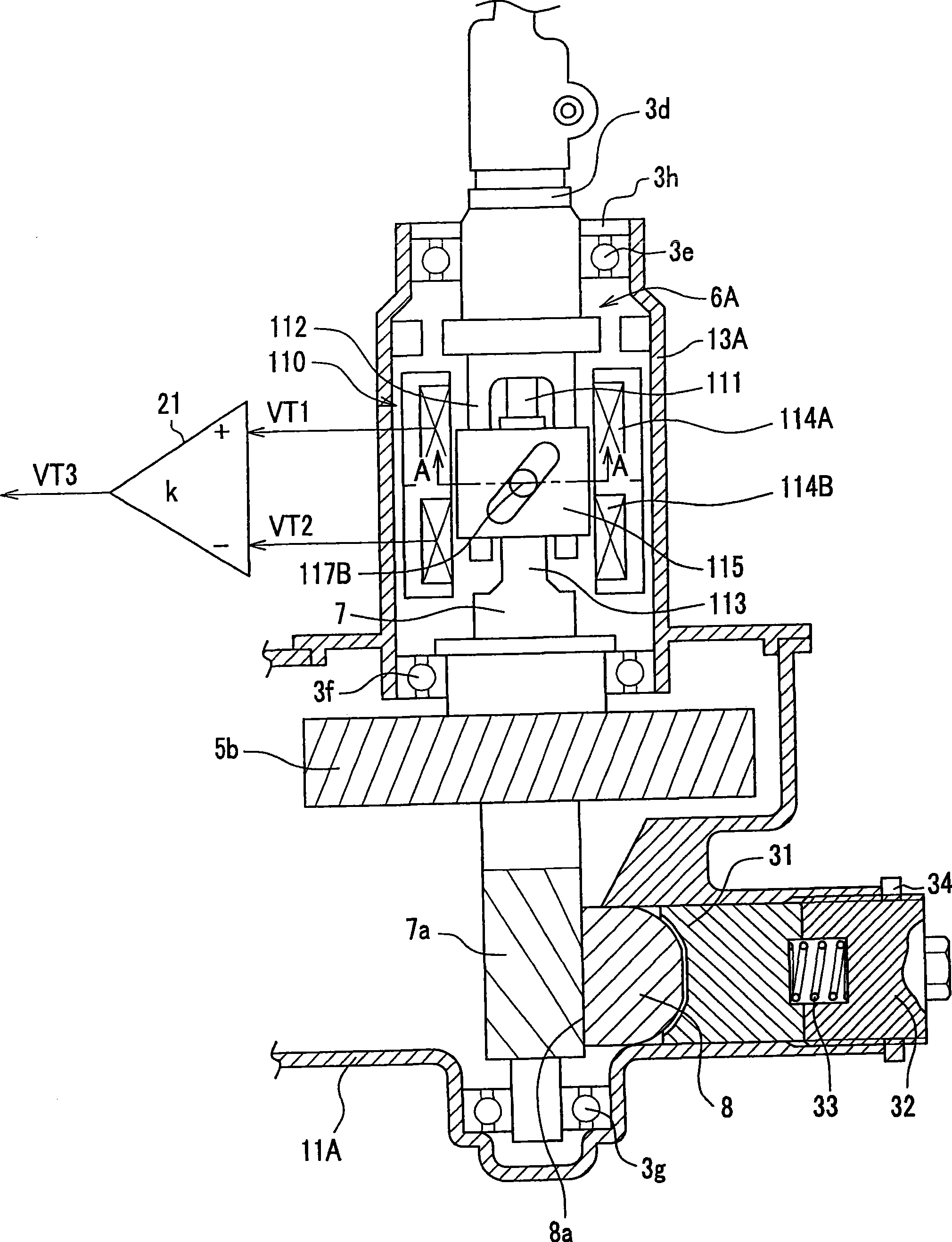
[0066] figure 2 It is a side view of the torque sensor and the vicinity of the pinion of the steering gear box in FIG. 1 .
[0067] As shown in FIG. 1, an electric power steering device 100A uses two universal joints 3b to connect the steering wheel shaft 3a, the shaft 3c, and the input shaft 3d provided with the steering wheel (operating member) 3. The input shaft 3d is connected to the small The pinion shaft 7 is connected. In addition, the pinion 7a provided at the lower end of the pinion shaft 7 meshes with the rack 8a of the rack shaft 8 that can move back and forth in the vehicle width direction. The rods 9, 9 connect the left and right front wheels 1L, 1R.
[0068] Such as figure 2 As shown, the rack shaft 8 is supported by th...
no. 2 approach 》
[0193] Next, an electric power steering system according to a second embodiment of the present invention will be described with reference to FIG. 14 .
[0194] 14 is a configuration diagram of an electric power steering device according to a second embodiment of the present invention. The electric power steering device 100B of the present embodiment is of a type in which the motor 4 assists in driving the rack shaft 8 via the ball screw 5c.
[0195] The difference from the first embodiment is that instead of the electric motor 4 driving the pinion shaft 7 via the worm gear 5a and the worm gear 5b, in this embodiment, the electric motor 4 drives the reduction mechanism (auxiliary gear) composed of the worm gear 5a and the worm gear 5b The torque transmission mechanism) 5B and the ball screw 5c are driven by directly converting the rotational motion of the ball screw 5c into the linear motion of the rack shaft 8 .
[0196] Another point of difference is that instead of the torq...
no. 3 approach 》
[0209] Second, refer to Figure 15 At the same time, an electric power steering system according to a third embodiment of the present invention will be described.
[0210] Figure 15 It is a configuration diagram of an electric power steering system according to a third embodiment of the present invention. The electric power steering device 100C of the present embodiment is of a type that assists in driving the steering shaft 3 a by the electric motor 4 via the worm gear 5 a and the worm gear 5 b.
[0211] The difference from the first embodiment is that instead of the electric motor 4 driving the pinion shaft 7 through the worm gear 5a and the worm gear 5b, in this embodiment, the electric motor 4 drives the pinion shaft 7 through the speed reduction mechanism (auxiliary rotation mechanism) composed of the worm gear 5a and the worm gear 5b. Torque transmission mechanism) 5A drives the steering wheel shaft 3a.
[0212] Another point of difference is that instead of the torq...
PUM
 Abstract
Description
Claims
Application Information
 - R&D
- Intellectual Property
- Life Sciences
- Materials
- Tech Scout
- Unparalleled Data Quality
- Higher Quality Content
- 60% Fewer Hallucinations
Browse by: Latest US Patents, China's latest patents, Technical Efficacy Thesaurus, Application Domain, Technology Topic, Popular Technical Reports.
© 2025 PatSnap. All rights reserved.Legal|Privacy policy|Modern Slavery Act Transparency Statement|Sitemap|About US| Contact US: help@patsnap.com


