Movement mechanism of cam type pipe robot

A pipeline robot and motion mechanism technology, applied in the direction of special pipes, pipe components, mechanical equipment, etc., can solve the problems of small friction, difficulty in adapting to pipe bends, poor adaptability to pipe diameter changes of micro-miniature pipe robots, etc., to achieve Improve adaptability, solve poor pipeline adaptability, and enhance the ability to actively adapt to large-scale pipe diameter changes

Inactive Publication Date: 2009-05-13
NAT UNIV OF DEFENSE TECH
View PDF0 Cites 12 Cited by
  • Summary
  • Abstract
  • Description
  • Claims
  • Application Information

AI Technical Summary

Problems solved by technology

[0003] The walking device of the pipeline robot is the walking power part used in the pipeline robot. Currently, the pipeline robot’s travel modes mainly include wheeled straight forward, wheeled screw propulsion and peristaltic. No matter which method is used, the traction force of the pipeline robot is It is provided by the friction force between the walking mechanism and the pipe wall, so if you want to increase the traction force, you must increase the friction force accordingly. However, in practical applications, it is hoped to obtain a large traction force while having a small friction force. This is A Contradiction to be Solved in the Field of Miniature Pipeline Robots
Another contradiction is the contradiction between the diameter of the pipeline robot itself and the size of the pipe diameter change range that it can adapt to. The existing pipeline robots with good pipe diameter change adaptability have a diameter of more than 50mm, which is difficult to adapt to. Smaller pipe diameters and curved pipes with greater curvature
At the same time, the micro-pipeline robot (diameter less than 20mm) has poor adaptability to pipe diameter changes, and can only have a small change range near its own outer diameter.

Method used


Image

  • Movement mechanism of cam type pipe robot
  • Movement mechanism of cam type pipe robot
  • Movement mechanism of cam type pipe robot

Examples


Embodiment Construction

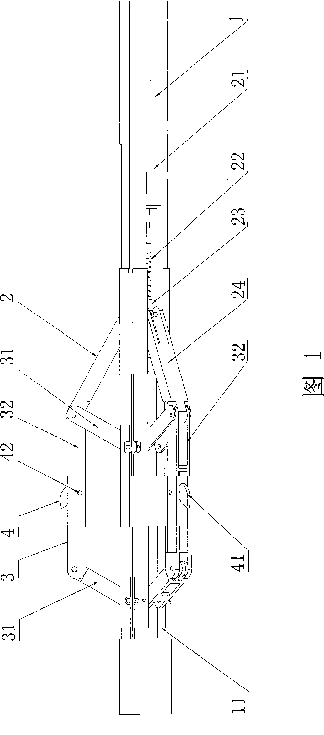
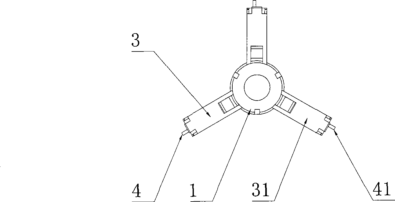
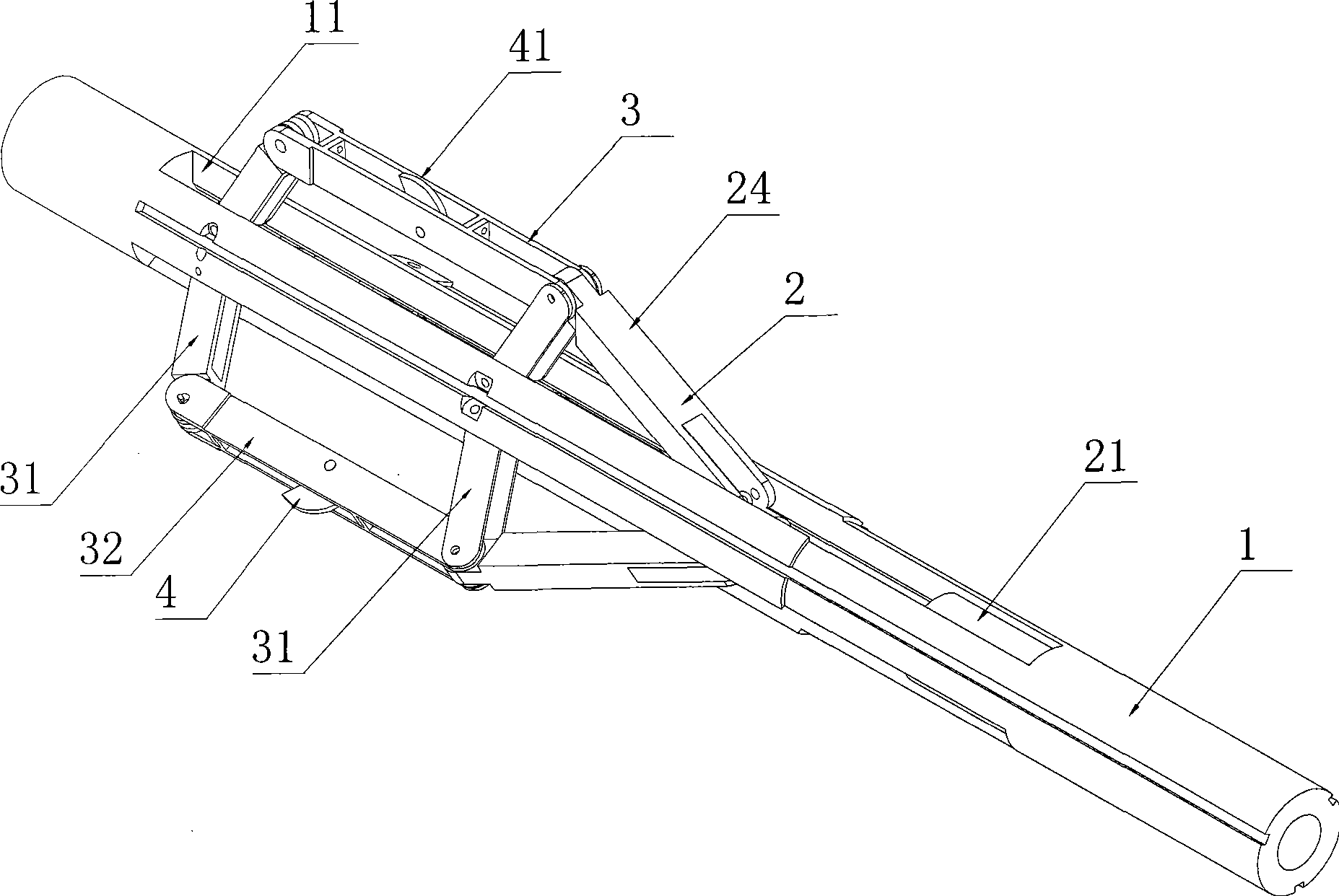
[0031] Figure 1 to Figure 7 As shown, the present invention discloses a cam-type pipeline robot motion mechanism, including a cylindrical support 1, on which three groups of parallelogram four-bar mechanisms 3 arranged at equal intervals along the circumferential direction and a group of driving parallelogram four-bar mechanisms 3 are installed. The drive mechanism 2 for the four-bar mechanism 3 to expand or retract, the cylindrical support 1 is provided with an accommodating groove 11 for accommodating the parallelogram four-bar mechanism 3 in the folded state, and each parallelogram four-bar mechanism 3 includes two rockers 31 and the connecting rod 32 connected between the two rocking bars 31, the two rocking rods 31 are respectively hinged with the cylindrical support 1, the connecting rod 32 is parallel to the central axis of the cylindrical support 1, and the middle parts of each connecting rod 32 are installed Cam mechanism 4 is arranged, and cam mechanism 4 comprises ...


PUM


Abstract

The invention discloses a cam type pipeline robot moving mechanism which includes a cylinder bracket that is provided with three groups of parallelogram four bar linkages arranged along the circumferencial direction in an equidistant way and a drive mechanism used for driving the three groups of parallelogram four bar linkages to unfold or furl, wherein, each of the parallelogram four bar linkages comprises two rockers and a connecting rod connected between the two rockers which are respectively articulated with the cylinder bracket, and one of the rockers is connected with the drive mechanism; the middle part of the connecting rod is provided with a cam mechanism that comprises a cam, a pin roll and a torsional spring arranged on the pin roll, wherein, the cam is articulated in the middle of the connecting rod by the pin roll, one end of the torsional spring is fixedly connected with the connecting rod, and the other end is fixedly connected with the cam; the cam keeps to extend out of the connecting rod under the action of pretightening force of the torsional spring. The device utilizes the self-locking of the cam to improve the pulling capacity and uses the deformation of the parallelogram four bar linkages for enhancing the adaptive capacity for pipe diameter change.

Description

technical field [0001] The invention relates to a peristaltic pipeline robot, in particular to a cam-type pipeline robot motion mechanism. Background technique [0002] There are great difficulties and dangers in the operation in the micro-pipeline, and the micro-pipeline robot provides an effective technical way for it. At present, micro-miniature pipeline robots are mainly used in the detection of many small pipelines in nuclear power plants, thermal power plants, chemical industry, refrigeration and other industries, as well as various complex power system pipelines. Many countries attach great importance to the development of micro-pipeline robots, and have invested money and time in research on this type of robot technology, and have achieved certain research results. The research laboratory of DENSO CORP in Japan has developed a laminated piezoelectric actuator microrobot, which consists of four parts: a 60um thick sheet metal substrate, two eddy current sensors to de...

Claims


Application Information

Patent Timeline
Patent Type & Authority Applications(China)
IPC IPC(8): F16L55/32F16L101/30
Inventor 尚建忠罗自荣乔晋崴杨军宏张详坡
Owner NAT UNIV OF DEFENSE TECH
Why Eureka
Try Eureka