Thyristor resistor transition switching on-load tap-changer

A technology of changeover switch and on-load tap, which is applied in the direction of electronic switches, circuits, inductors, etc., to achieve the effects of reliable operation, reduced workload and cost, and simple structure

Active Publication Date: 2009-05-13
SHANGHAI HUAMING POWER EQUIP CO LTD +1
View PDF0 Cites 16 Cited by
  • Summary
  • Abstract
  • Description
  • Claims
  • Application Information

AI Technical Summary

Problems solved by technology

[0005] The technical problem to be solved by the present invention is to provide a thyristor resistance transition switching on-load tap-changer to solve the many shortcomings of the existing resistance transition and mechanical switch contact switching on-load tap-changers

Method used


Image

  • Thyristor resistor transition switching on-load tap-changer
  • Thyristor resistor transition switching on-load tap-changer
  • Thyristor resistor transition switching on-load tap-changer

Examples


Embodiment 1

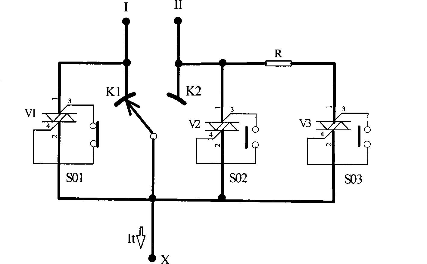
[0025] This embodiment describes a thyristor resistance transition combination on-load tap changer, which includes a switching circuit, and the switching circuit includes a thyristor switching circuit, a transition resistance branch formed by a transition thyristor switch and a transition resistance.

[0026] see figure 1 A thyristor changeover switch branch is connected to the fixed contacts of the odd-number tap and the even-number tap, and a transition resistance branch composed of a transition thyristor switch and a transition resistor is connected to the even-number tap side.

[0027] When switching, first connect the gate of the corresponding thyristor, so that the thyristor connects the transition resistance branch and passes the transformer current between the original tap and the new tap; then disconnect the two thyristor switches connected in series in the transition resistance branch as required. One gate circuit can complete the switching from the original tap to t...
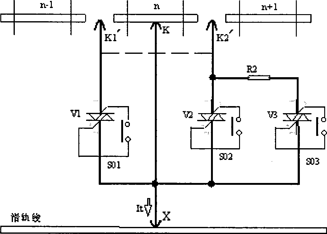
Embodiment 2

[0037] This embodiment describes the thyristor resistance transition compound on-load tap-changer (see figure 2 ). Both transition moving contacts are connected with a thyristor changeover switch branch, and one of the moving contacts is also connected with a transition resistance branch. When the moving contact moves to the switching position, first connect the gate of the relevant thyristor switch, so that the thyristor switch connects the transition resistance branch and passes the transformer current between the original tap and the new tap; and then disconnects the thyristor switch as required The gate circuit of one of the two thyristor switches connected in series in the transition resistance branch can complete the switching from the original tap to the new tap when the transformer current appears to cross zero. It is not necessary to consider the zero-crossing point of the current when turning on and off the gate circuit of the thyristor switch, and the gate of the ...


PUM


Abstract

The invention provides a thyristor resistance transition shifting on-load tap-changer, comprising a shifting circuit. The invention is characterized in that the shifting circuit comprises a thyristor shifting switch circuit and a transition resistance branch which consists of a transitional thyristor switch and a transitional resistance. Compared with the existing mechanical switch resistance transition shifting on-load tap-changer, the thyristor resistance transition shifting on-load tap-changer has the advantages as follows: 1. the no-arc shifting is realized, and the electric service life of the switch is not restricted by the shifting times; 2. during the shifting process, the voltage does not exceed the conduction voltage decrement (1 to 2V) of the thyristor when the movable contact of each mechanical switch and the fixed contact thereof are turned on or turned off; furthermore, the recovery voltage of the traditional resistance transitional on-load tap-changer can be one time or more times of the step voltage; the mechanical switch bears extremely different tasks between the thyristor resistance transition shifting on-load tap-changer and the traditional resistance transitional on-load tap-changer; 3. the work load and the cost for maintenance and keeping are reduced.

Description

Background technique [0001] The invention relates to the technical field of transformer on-load tap changers, in particular to a thyristor resistance transition switch on-load tap changer. Background technique [0002] The transformer on-load tap-changer with resistance transition and mechanical switch contact switching has been successfully developed by the Germans more than 80 years ago, and this technology has been used until now. The existing resistance transition, mechanical switch contact switching on-load tap-changer has the following deficiencies: [0003] 1. When switching, because the mechanical switch contacts are broken at random moments of the transformer sine wave current, arc burning will occur, which makes the electrical life of the switch short and prone to power supply failures. [0004] 2. The arcing generated by the diverter switch contacts is easy to pollute the transformer oil in the diverter switch oil chamber, which shortens the maintenance cycle and...

Claims


Application Information

Patent Timeline
Patent Type & Authority Applications(China)
IPC IPC(8): H01F29/04H03K17/687
Inventor 肖日明肖毅肖申
Owner SHANGHAI HUAMING POWER EQUIP CO LTD
Why Eureka
Try Eureka