Low surface roughness cast strip and method and apparatus for making the same

一种表面粗糙度、铸带的技术,应用在低表面粗糙度铸带及其生产和设备领域,能够解决不经济等问题

Active Publication Date: 2009-05-13
NUCOR CORP
View PDF7 Cites 7 Cited by
  • Summary
  • Abstract
  • Description
  • Claims
  • Application Information

AI Technical Summary

Problems solved by technology

Also, microcracks in the cast strip surface have become a problem
Microcracks can be reduced by reducing the casting speed and the heating rate of the cast strip, but it is not economical to achieve these conditions in production

Method used


Image

  • Low surface roughness cast strip and method and apparatus for making the same
  • Low surface roughness cast strip and method and apparatus for making the same
  • Low surface roughness cast strip and method and apparatus for making the same

Examples


Embodiment Construction

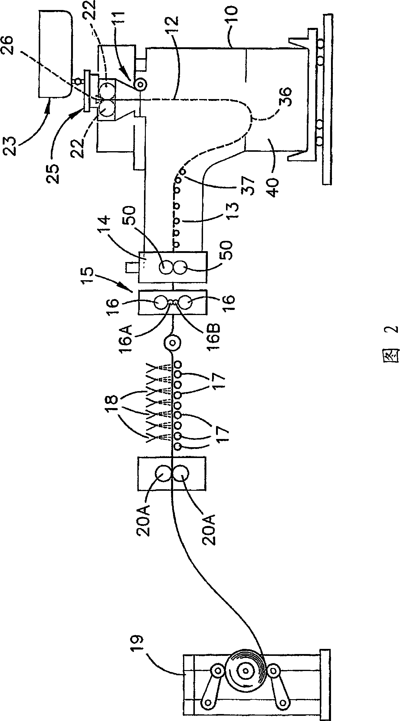
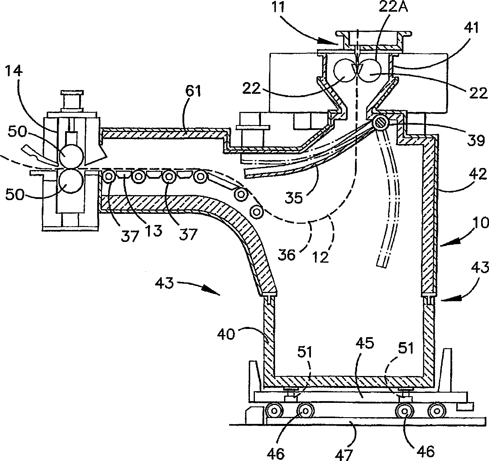
[0074] The illustrated casting and rolling equipment includes a twin-roll casting and rolling mill generally indicated by 11 for producing thin cast steel strip 12, which enters the transition path on the guide table 13 to the nip roll station 14. After exiting the nip roll station 14, the thin cast steel strip 12 enters and passes through the hot rolling mill 15 composed of the support roll 16 and the upper and lower work rolls 16A and 16B, where the thickness of the steel strip is reduced. After the thin cast steel strip 12 exits from the upper part of the hot rolling mill 15, it enters the output roller table 17, where it is forcedly cooled by a water spray nozzle 18, and then passes through a nip roller station 20 including a pair of nip rollers 20A to reach the coiling device 19.

[0075] The twin-roll casting-rolling mill 11 includes a main frame supporting a pair of transversely disposed casting rollers 22 having casting surfaces 22A and forming a nip between the casting su...


PUM

PropertyMeasurementUnit
roughnessaaaaaaaaaa
roughnessaaaaaaaaaa
roughnessaaaaaaaaaa

Abstract

A thin cast strip is formed having at least one microstructure selected from the group consisting of polygonal ferrite, acicular ferrite, Widmanstatten, bainite and martinsite, a surface roughness of less than 1.5 microns Ra and a scale thickness of less than about 10 microns by applying a mixture of water and oil on the work rolls of the hot rolling mill, passing the thin cast strip at a temperature of less than 1100 DEG C through the hot rolling mill while the mixture of oil and water is applied to the work rolls, and shrouding the thin cast strip from the casting rolls through the hot rolling mill in an atmosphere of less than 5 % oxygen to form the thin cast strip.

Description

Technical field [0001] The invention relates to a cast strip produced by a double-roll casting and rolling mill and a method and equipment for producing the cast strip. Background technique [0002] On the twin-roll casting mill, the molten metal is introduced between a pair of counter-rotating transverse casting rolls to cool the casting rolls so that the metal shell is solidified on the surface of the moving casting roll, and the metal shell is placed between the casting rolls. The nip between the casting rolls is combined together to produce a solid cast tape product, which is output downward from the nip between the casting rolls. [0003] The term "roll gap" is used here to refer to the general area where the two casting rolls are the closest to each other. The molten metal can be poured out of the ladle, through a metal conveying system consisting of a tundish and a core nozzle located above the roll nip, forming a molten metal casting pool, which is supported by the castin...

Claims


Application Information

Patent Timeline
Patent Type & Authority Applications(China)
IPC IPC(8): B21B1/26B21B1/46B21B27/10B21B37/00B21B45/02
CPCB21B2261/14B21B2027/103B21B1/46B21B27/10B21B1/463B21B1/26B22D11/06
Inventor 沃尔特·布莱杰德杰伊·J·翁德罗维克
Owner NUCOR CORP
Why Eureka
Try Eureka