Eureka AIR delivers breakthrough ideas for toughest innovation challenges, trusted by R&D personnel around the world.

Method and system for displaying television wall, and television wall control equipment

A display method and technology of a TV wall, applied in the field of electronic information, can solve problems such as limiting the scalability of the system, and achieve the effect of improving the display capability and the scalability.

Active Publication Date: 2009-05-20
GLOBAL INNOVATION AGGREGATORS LLC
View PDF0 Cites 37 Cited by
  • Summary
  • Abstract
  • Description
  • Claims
  • Application Information

AI Technical Summary

Problems solved by technology

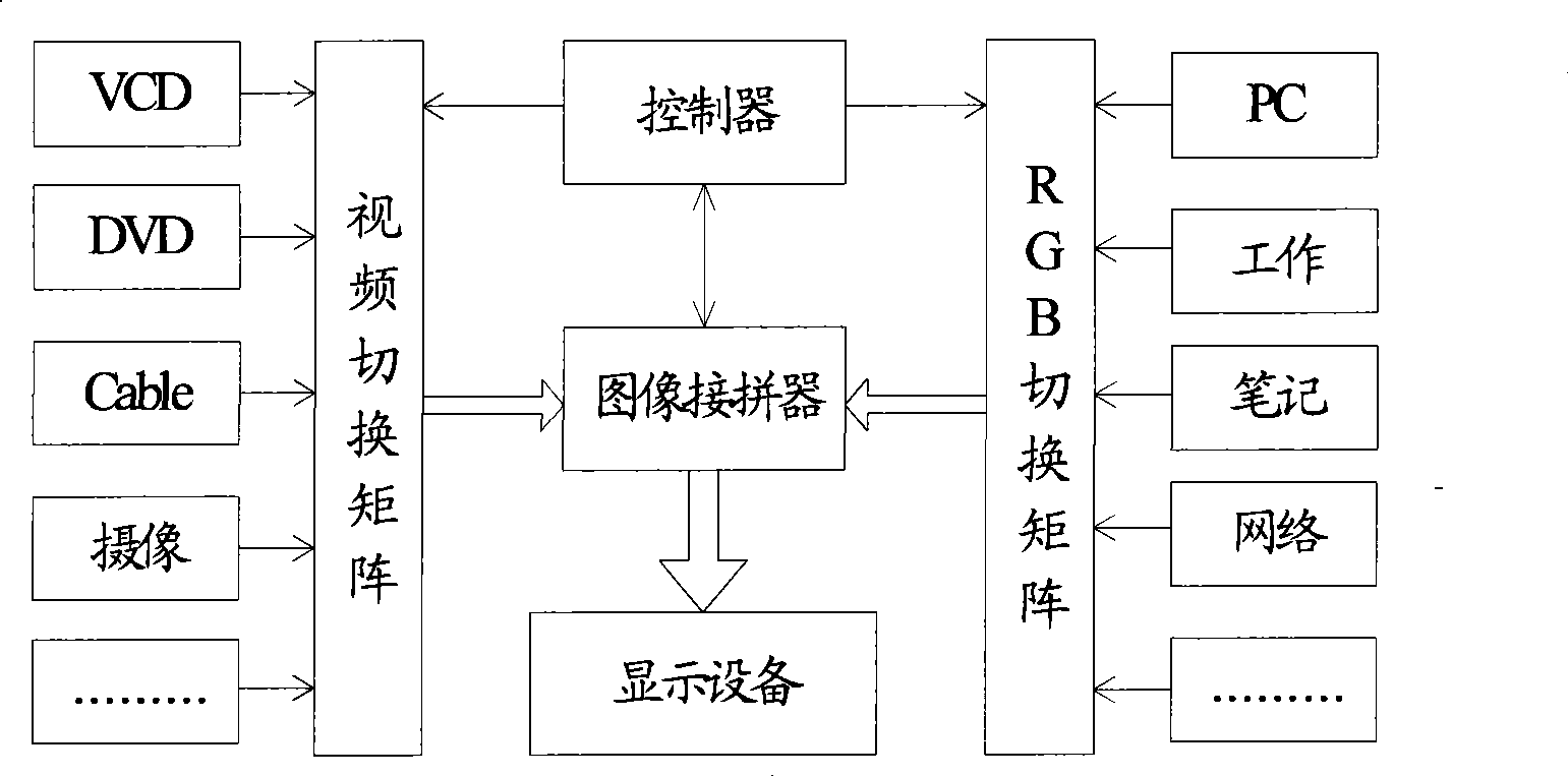
[0008] During the practice and research of the prior art, the inventor of the present invention found that: in the existing video wall display system technology, only a single The TV wall control module controls the display of the TV wall, so that the number of split screens supported by the system can only reach the number of split screens supported by a single TV wall control module, which limits the scalability of the system

Method used


Image

  • Method and system for displaying television wall, and television wall control equipment
  • Method and system for displaying television wall, and television wall control equipment
  • Method and system for displaying television wall, and television wall control equipment

Examples


Embodiment 1

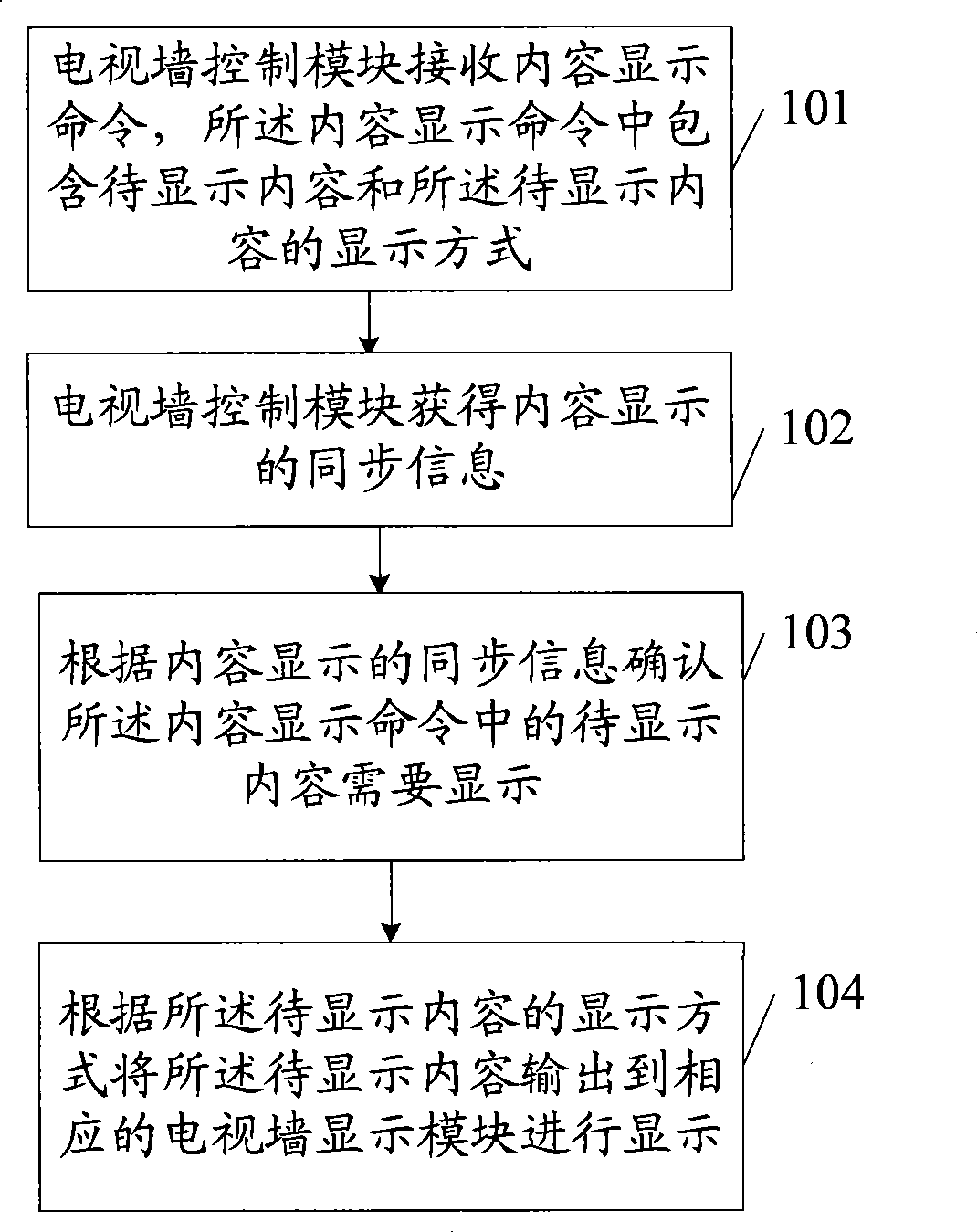
[0046] Embodiment 1. A video wall display method. The method of this embodiment is a method for a video wall display system, and may include multiple (at least two) video wall control modules. The flow chart is as follows figure 2 shown, including:

[0047] Step 101, the TV wall control module receives a content display command, the content display command includes the content to be displayed and the display mode of the content to be displayed;

[0048]It can be understood that the received content display command is a program source from the system, and the content display command can be a video display command, a subtitle display command, etc., and the content that may need to be displayed (such as video, subtitle, etc.) is included in the content display command. ) and the display mode of the content to be displayed, the display mode is one or more of the following: display parameters such as port information of content display, display size, display size, color, static di...

Embodiment 2

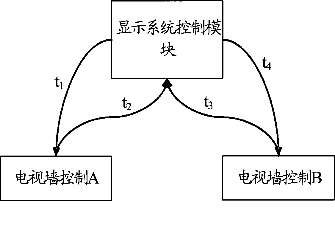
[0075] Embodiment 2. A video wall display method. In this embodiment, the content display command is a video display command, and in this embodiment, the synchronous information for content display is obtained through a third party controlling multiple (at least two) video walls. Module synchronization method is obtained, the signaling flow chart is as follows Figure 5 shown, including:

[0076] Step 201, the system control module holds a video wall conference, and sends a video wall display conference scheduling command to the MCU module through network transmission;

[0077] Step 202: The MCU module parses the command after receiving the video wall conference scheduling command, and obtains the terminal site information to be displayed. The MCU calls each terminal site of the video wall conference, and each terminal site joins the conference. The MCU module will report the system resources to the system control module. ;

[0078] Step 203, the system control module sends ...

Embodiment 3

[0086] Embodiment 3. A video wall display method. In this embodiment, the content display command is a subtitle display command, and in this embodiment, the synchronization information for content display is obtained through a third party controlling multiple (at least two) video walls. Synchronization of modules is obtained, while the third party refers to the system control module, the flow chart is as follows Figure 6 shown, including:

[0087] Step 301, start multiple video wall control modules, report video wall resources to the system control module, and the system control module synchronizes the multiple video wall control modules, and sends corresponding synchronization information for content display. The specific method is as follows: Example 1.

[0088] Step 302 , the system control module sends a subtitle display command to multiple video wall control modules, and the subtitle display command includes display subtitles and a display mode of the display subtitles....


PUM


Abstract

The embodiment of the invention provides a video-wall display method, a video-wall display system and a video-wall control device, which are applied to the technical field of electronic information. The video-wall display method comprises outputting a content to be displayed through adopting a piece of obtained synchronizing information for content display to confirm that the content to be displayed needs to be output and displayed, so that when a plurality of video-wall control modules exist, each video-wall control module can only output the corresponding content to be displayed when the video-wall control module outputs synchronizing information for the content display of the content to be displayed synchronously with other video-wall control modules, thus the plurality of the video-wall control modules can control the video-wall display, each video-wall control module is corresponding to one or more split screens of a multi-screen display, the number of the split screens is increased, and the expansibility of the video-wall display system is improved so as to provide support for the multi-screen display of an image with an ultrahigh image resolution; and the display capability of the system is improved simultaneously.

Description

technical field [0001] The invention relates to the technical field of electronic information, in particular to a video wall display method, system and video wall control equipment. Background technique [0002] With the advent of the information age, especially the development of network technology, the need for information sharing and information synthesis has become increasingly prominent. Video conferencing products are developing with the rapid development of various information technologies, and video wall display systems have emerged as the times require. , thereby satisfying people's demand for super-resolution image display. The video wall display system can display video data and image signals from personal computers (PCs), workstations, video cameras, DVD players, video players, etc., realize switching and mixed display of computer data, images, and video images, and realize multiple windows. Signal display and information integration, is an information integrati...

Claims


Application Information

Patent Timeline
IPC IPC(8): G09G5/12G09G5/14
Inventor 颜军汪子强徐凌峰
Owner GLOBAL INNOVATION AGGREGATORS LLC
Why Eureka
Eureka Blog
Learn More