Filling method for reducing discharge of methane using wind force intensified ventilation

A methane and wind technology, applied in the field of quasi-aerobic landfill process, can solve the problems of increasing power consumption and management costs, and achieve the effects of speeding up the stabilization process, saving energy and reducing emissions

CN101439344AInactive Publication Date: 2009-05-27TONGJI UNIV
0 Cites 17 Cited by

Patent Information

Authority / Receiving Office
CN · China
Patent Type
Applications(China)
Current Assignee / Owner
Publication Date
2009-05-27
Estimated Expiration
Not applicable · inactive patent

Smart Images

  • Figure 1
    Figure 1
  • Figure 2
    Figure 2
  • Figure 3
    Figure 3
Patent Text Reader

Abstract

A landfill method for strengthening ventilation and reducing the drainage of methane by taking advantage of wind power relates to a quasi-aerobic garbage landfill process. The landfill method is characterized in that a wind housing (1) is mounted at the tail end of a percolating liquid collecting main pipe (4), wherein, the ratio of an inlet diameter and an outlet diameter equal of the wind housing (1) ranges from to 8:1 to 4:1; a wind cap (2) is mounted at the top end of a vertical air duct (3) and rotates under double drive of external natural wind and difference between internal temperature and external temperature of a landfill body, so as to generate negative pressure and centrifugal force, continuously draw out landfill air in the air duct (3), drive the wind cap (2) at the tail end of the percolating liquid collecting main pipe (4) to continuously suck outside air into a garbage body, thereby forming a sustaining and efficient ventilating system, promoting aerobic decomposition and stability of garbage, and greatly reducing methane discharge. The method consumes no power, thereby greatly reducing the discharge of the quasi-aerobic garbage landfill methane and achieving the energy conservation and the drainage reduction. The invention has the advantages of simple process, convenient disassembly and assembly, low cost, and can be widely applied to domestic garbage landfill yards.
Need to check novelty before this filing date? Find Prior Art

Description

technical field

[0001] The invention relates to a landfill method for reducing methane emission by using wind power to enhance ventilation, and relates to a quasi-aerobic landfill process. The landfill method of the invention can realize greenhouse gas emission reduction. technical background

[0002] Methane is an important greenhouse gas with a global warming potential (GWP) 23 times that of carbon dioxide, accounting for 20% of global warming. Currently, CH 4 The emission is about 500 million tons, of which 22-36 million tons come from landfill sites, and the control of landfill CH 4 Emissions are an effective measure to control the greenhouse effect.

[0003] The quasi-aerobic landfill technology is an economical and mature municipal solid waste treatment method. Its basic structure includes perforated leachate collection pipes and air ducts. The end of the leachate collection pipe communicates with the outside atmosphere; one end of the air guide pipe communicates wi...

Examples

Embodiment 1

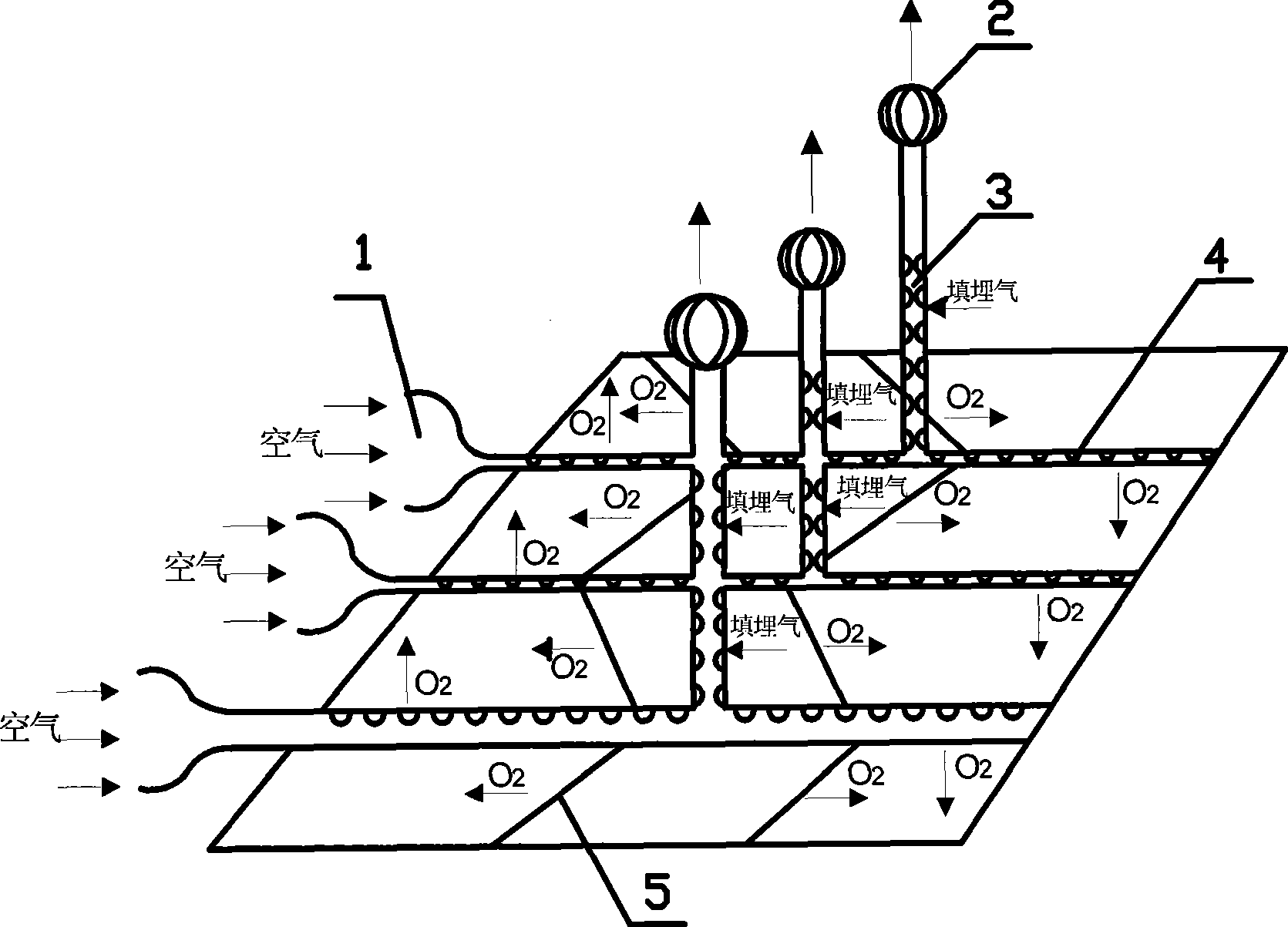
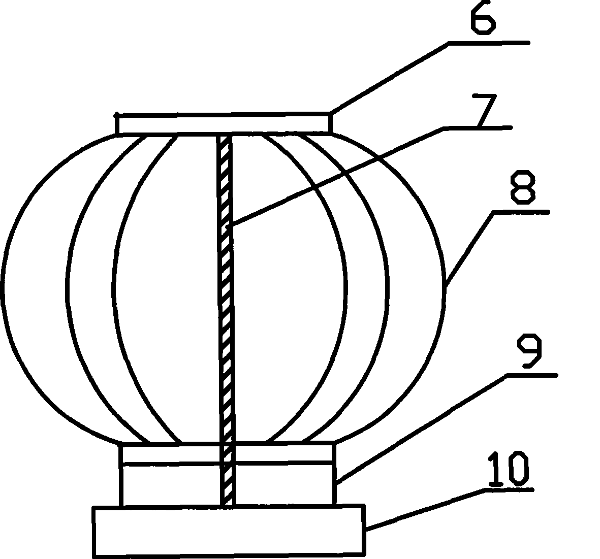
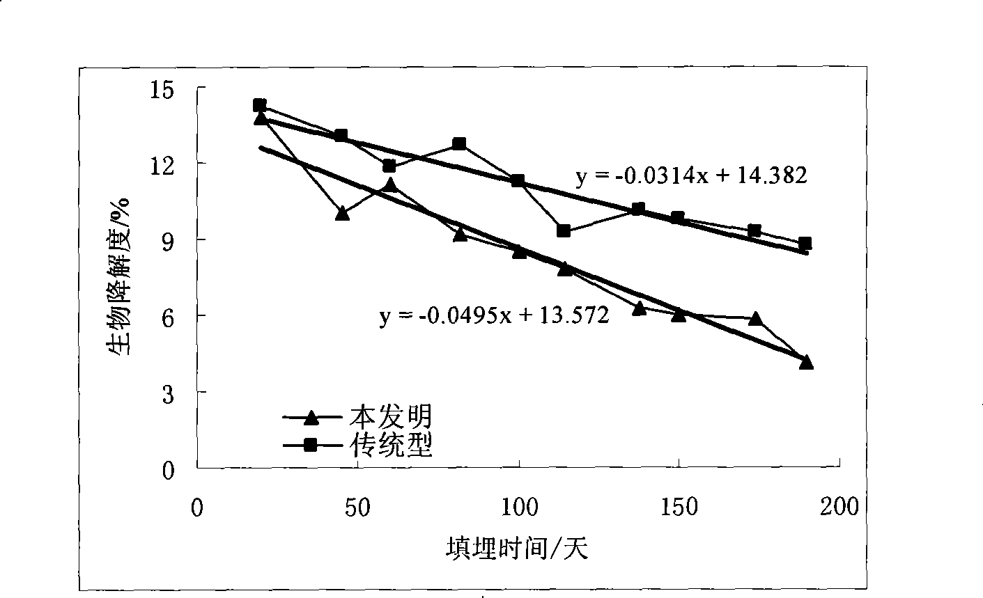
[0022] Please refer to the attached figure 1 , 2, 3, 4, 5, where figure 1 A structural schematic diagram of the implementation of the present invention is given.

[0023] Firstly, two quasi-aerobic landfill simulation devices with the same internal structure and the same scale as 2m×1m×1.5m are established. One is a traditional quasi-aerobic landfill structure, and the other is a structurally improved landfill method according to the present invention. . The same structure is: the main leachate collection pipe 4 and the leachate collection branch pipe 5 are upper semicircular perforated pipes with a hole diameter of 12.5mm and a hole spacing of 50mm. The leachate collection main pipe 4 and the leachate collection branch pipe 5 adopt branched distribution, that is, three leachate collection main pipes 4 with a diameter of 150 mm are used, and two diameters of 100 mm are evenly distributed on both sides of each leachate collection main pipe 4 The leachate collection branch pi...