
Engine oil sump

An engine oil and oil pan technology, which is applied in the direction of engine components, machines/engines, and engine lubrication, can solve problems such as increased manufacturing difficulty and cost, complex engine structure, and large oil pressure loss, saving power and reducing The space occupied, the effect of prolonging the service life

Inactive Publication Date: 2009-05-27
CHERY AUTOMOBILE CO LTD
View PDF0 Cites 4 Cited by
  • Summary
  • Abstract
  • Description
  • Claims
  • Application Information

AI Technical Summary

Problems solved by technology

[0002] The oil filter of a traditional engine needs to be installed on the cylinder block or frame through the oil filter seat, which takes up a lot of space. For a compact engine, it greatly increases its manufacturing difficulty and cost; the oil passes through the oil pan, engine The oil pump, the oil passage of the cylinder frame, and the oil filter seat can reach the filter, and then return to the cylinder oil passage through the oil filter seat, resulting in a very complicated engine structure and poor workmanship, and the oil passage is too long The pressure loss of the engine oil is relatively large; after a period of use, the entire oil filter needs to be replaced, which is inconvenient to disassemble and replace, and the maintenance cost is high

Method used


Image

  • Engine oil sump
  • Engine oil sump

Examples


Embodiment 1

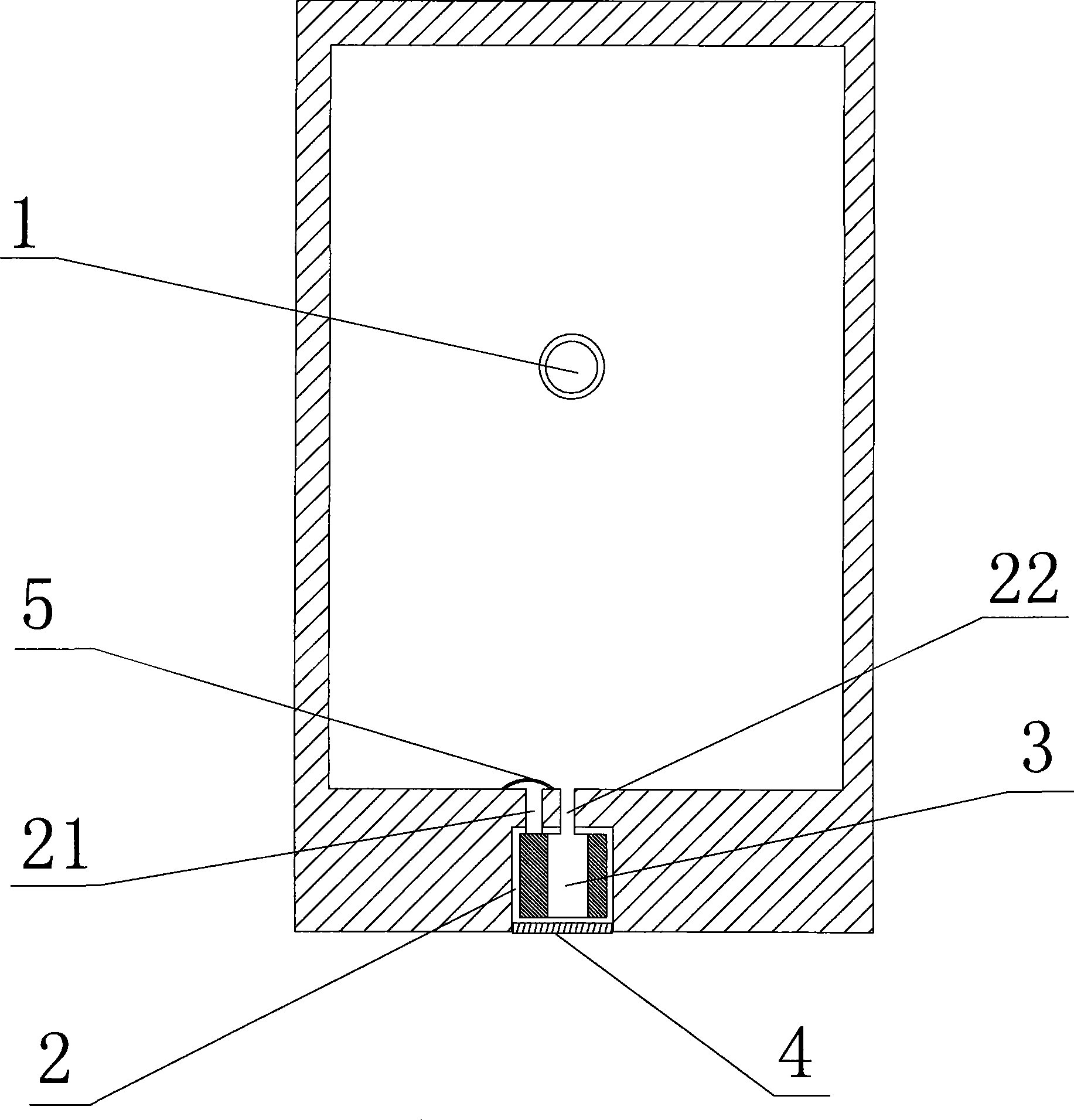
[0020] The bottom of the engine oil pan in this embodiment is provided with an oil drain plug 1, and the side wall is provided with an accommodating hole 2 that can accommodate the oil filter element 3, and the end of the accommodating hole 2 facing the inside of the oil pan is provided with an oil plug. The oil passage inlet 21 and the oil passage outlet 22, the other end is threaded to install the oil filter cover 4, the oil filter element 3 is installed inside the accommodation hole 2, and the oil passage inlet 21 of the accommodation hole 2 is equipped with a filter screen 5.

[0021] The engine oil passage of this embodiment is arranged like this: After the engine oil enters the oil pan from the oil passage of the cylinder body, it passes through the oil passage of the oil pan, the oil filter, the oil pump and the cylinder body frame in turn, and finally returns to the cylinder body Oil passage, the length of the oil passage of the whole engine is greatly shortened compar...

Embodiment 2

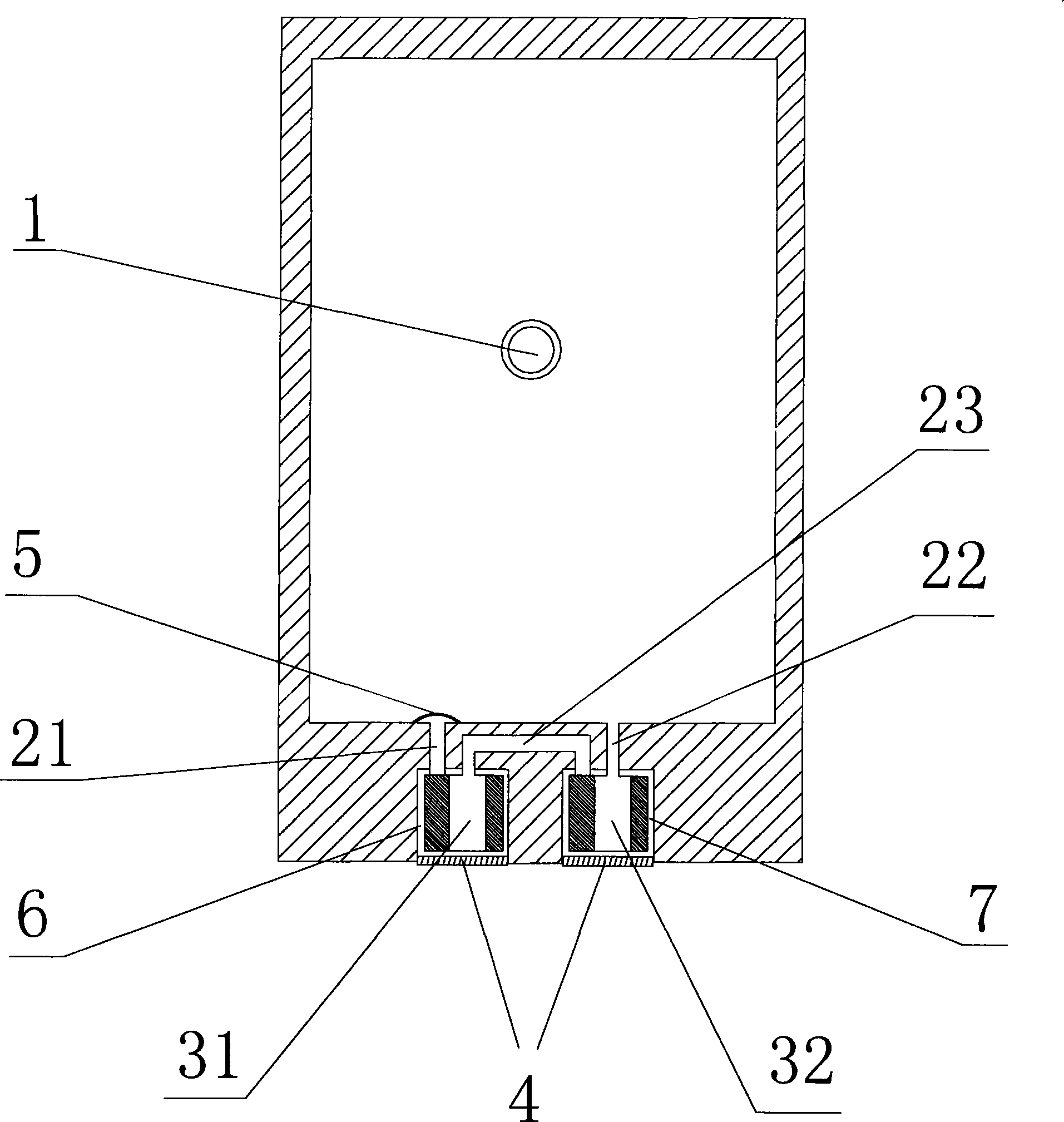
[0023] The bottom of the engine oil pan in this embodiment is provided with an oil drain screw plug 1, and the side wall is provided with two accommodating holes 6, 7 that can accommodate the oil primary filter element 31 and the engine oil fine filter element 32. The accommodating hole 6 has an oil inlet 21 at one end facing the oil pan, the accommodating hole 7 has an oil outlet 22 at one end facing the oil pan, and the other ends of the accommodating holes 6 and 7 are threaded. Install the oil filter cover 4, install the primary oil filter element 31 and the fine oil filter element 32 inside the two accommodation holes 6 and 7 respectively, and there is an oil passage between the two accommodation holes 6 and 7 23 are connected, and filter screen 5 is installed at oil inlet 21 places.

[0024] The engine oil passage of this embodiment is arranged like this: After the engine oil enters the oil pan from the oil passage of the cylinder body, it passes through the oil pan, the ...


PUM


Abstract

The invention aims to provide a crankcase oil tray of an engine with convenient production and low use cost and maintenance cost. A purge cock is arranged on the bottom of the crankcase oil tray of the engine, particularly, an oil filter is integrated in the wall of the crankcase oil tray. The wall of the crankcase oil tray is provided with an accommodating hole for accommodating a filter element of the oil filter; one end of the accommodating hole towards the inside of the crankcase oil tray is provided with an oil duct inlet and an oil duct outlet, while the other end is provided with a cover of the oil filter; and the filter element of the oil filter is arranged inside the accommodating hole. The invention makes the oil filter and related oil duct integrated on the crankcase oil tray of the engine to save space for independently mounting the filter and greatly shorten a cylinder body and the oil duct on a frame, so that pressure loss of oil can be reduced, and manufacturability can be optimized; cost for an oil filter seat is saved; the filter element of the oil filter can be directly arranged on the crankcase oil tray, the filter element can be changed by opening the cover from the outside when the oil filter is changed, the operation is convenient, and maintenance cost can be greatly reduced.

Description

technical field [0001] The invention belongs to the field of automobile manufacturing, and more specifically relates to an oil pan of an automobile engine. Background technique [0002] The oil filter of a traditional engine needs to be installed on the cylinder block or frame through the oil filter seat, which takes up a lot of space. For a compact engine, it greatly increases its manufacturing difficulty and cost; the oil passes through the oil pan, engine The oil pump, the oil passage of the cylinder frame, and the oil filter seat can reach the filter, and then return to the cylinder oil passage through the oil filter seat, resulting in a very complicated engine structure and poor workmanship, and the oil passage is too long The oil pressure loss is relatively large; after a period of use, the entire oil filter needs to be replaced, which is inconvenient to disassemble and replace, and the maintenance cost is high. Contents of the invention [0003] The purpose of the ...

Claims


Application Information

Patent Timeline
Patent Type & Authority Applications(China)
IPC IPC(8): F01M11/00F01M11/03
Inventor 常鹏飞罗春
Owner CHERY AUTOMOBILE CO LTD
Learn More