Implementing method and apparatus of stepless speed regulating eccentric swinging type internal combustion engine
A technology of stepless speed regulation and eccentric swing, applied in the direction of machines/engines, mechanical equipment, etc., to achieve the effects of reducing heat generation, wear, weight and cost
- Summary
- Abstract
- Description
- Claims
- Application Information
AI Technical Summary
Problems solved by technology
Method used
Image
Examples
Embodiment 1
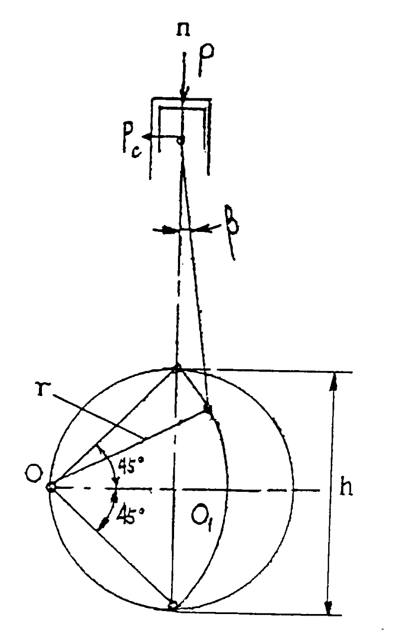
[0044] Such as figure 1 , 2 shown.
[0045] A method for realizing a stepless speed regulation eccentric swing internal combustion engine comprises the following steps:
[0046] First, make the crank of the internal combustion engine swing eccentrically around a fulcrum on one side of the cylinder axis, as figure 2 shown;
[0047] Secondly, the eccentrically oscillating crank drives the first drive shaft to reciprocate, and at the same time connects the first drive shaft to the second drive shaft through a direction-changing mechanism, thereby alternately driving to ensure that the first drive shaft can have a continuous swing during the reciprocating swing. power output, the first drive shaft and the second drive shaft continuously drive the output shaft through a linkage mechanism with a one-way transmission device for continuous directional output;
[0048] Third, stepless speed regulation is realized by adjusting the crank lengths of the first drive shaft and the sec...
Embodiment 2
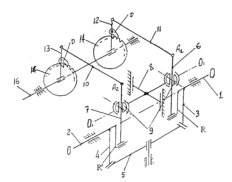
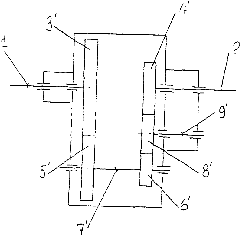
[0051] Such as image 3 , 4 , 5, and 6.
[0052] An eccentric oscillating internal combustion engine with a pulsating stepless speed regulation transmission, comprising an internal combustion engine body and a transmission device connected to the internal combustion engine body, wherein the internal combustion engine body further includes a cylinder and a piston located in the cylinder, the piston is connected with a connecting rod, and the The connecting rod is connected to the crank that swings around the fulcrum, the crank is connected to the input shaft of the transmission device, and the output shaft of the transmission device is connected to the driven parts. The transmission device is a pulse type stepless speed regulating device; the pulse type The stepless speed regulating device includes two coaxial first drive shaft 1 and the second drive shaft 2, the first drive shaft 1 and the second drive shaft 2 serve as the input shaft of the pulsating stepless speed regulatin...
Embodiment 3
[0067] As shown in Figure 7.
[0068] A transmission device (Fig. 7) of a four-stroke four-cylinder single-row internal combustion engine contains cylinders P1, P2, P3, P4 numbered according to their working order. The pulsating stepless speed regulating device is installed in the transmission device in the following manner; cylinders P4 and P2 are located on one side of the pulsating stepless speed regulating device, and cylinders P1 and P3 are located on the other side. The drive shaft 1 and 2 of the pulsating stepless speed regulating device are connected with the common connecting rod 3 and the swing crank 4, and the swing range of the crank 4' is α=90°.
[0069] In order to drive the flywheel 26 (without which the internal combustion engine cannot work), there is a crank rocker mechanism, which is connected to the input shaft 1, the transmission ratio of this mechanism is determined in the following way: when the rocker arm 27 swings from one extreme position to the other...
PUM
 Abstract
Description
Claims
Application Information
 - R&D
- Intellectual Property
- Life Sciences
- Materials
- Tech Scout
- Unparalleled Data Quality
- Higher Quality Content
- 60% Fewer Hallucinations
Browse by: Latest US Patents, China's latest patents, Technical Efficacy Thesaurus, Application Domain, Technology Topic, Popular Technical Reports.
© 2025 PatSnap. All rights reserved.Legal|Privacy policy|Modern Slavery Act Transparency Statement|Sitemap|About US| Contact US: help@patsnap.com


