Axial-flow fan and fan blade of centrifugal fan

A technology of axial flow fan and centrifugal fan, which is applied to components of pumping devices for elastic fluids, non-variable pumps, machines/engines, etc., can solve problems such as deposition, reduce pressure difference, and improve power consumption and noise quality, and the effect of eliminating the backflow phenomenon

Inactive Publication Date: 2009-05-27
ZHONGSHAN BROAD OCEAN
View PDF0 Cites 21 Cited by
  • Summary
  • Abstract
  • Description
  • Claims
  • Application Information

AI Technical Summary

Problems solved by technology

[0002] like figure 1 As shown, the blade of the existing axial flow fan has a front edge portion 1 in the direction of air inflow and a rear edge portion 2 in the direction of air outflow. The design of the edge part 2 is conducive to the outflow of air. Experiments have proved that: 1) when the fan blade rotates, the air flow at the rear edge of the fan blade is affected by the increased rotational kinetic energy, resulting in separation of the air flow in the boundary layer during the process of the air flow flowing out of the rear edge part 2 Bringing backflow phenomenon, it is easy to deposit a large amount of dust 4 on the rear edge 2 of the windward side 3. In the experiment, we can easily find the above described situation from the cooling axial flow fan on the computer.

Method used


Image

  • Axial-flow fan and fan blade of centrifugal fan
  • Axial-flow fan and fan blade of centrifugal fan
  • Axial-flow fan and fan blade of centrifugal fan

Examples


Embodiment 1

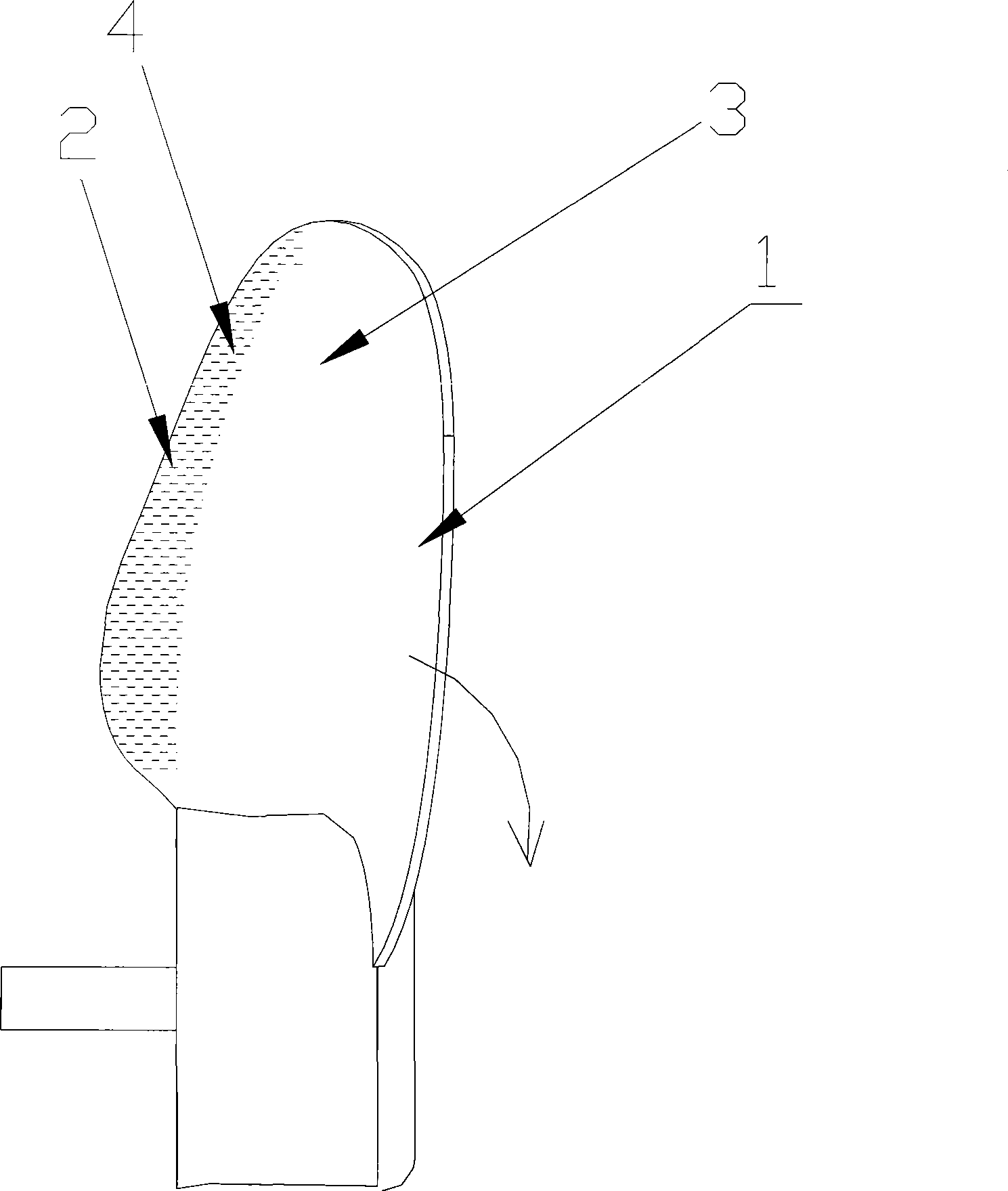
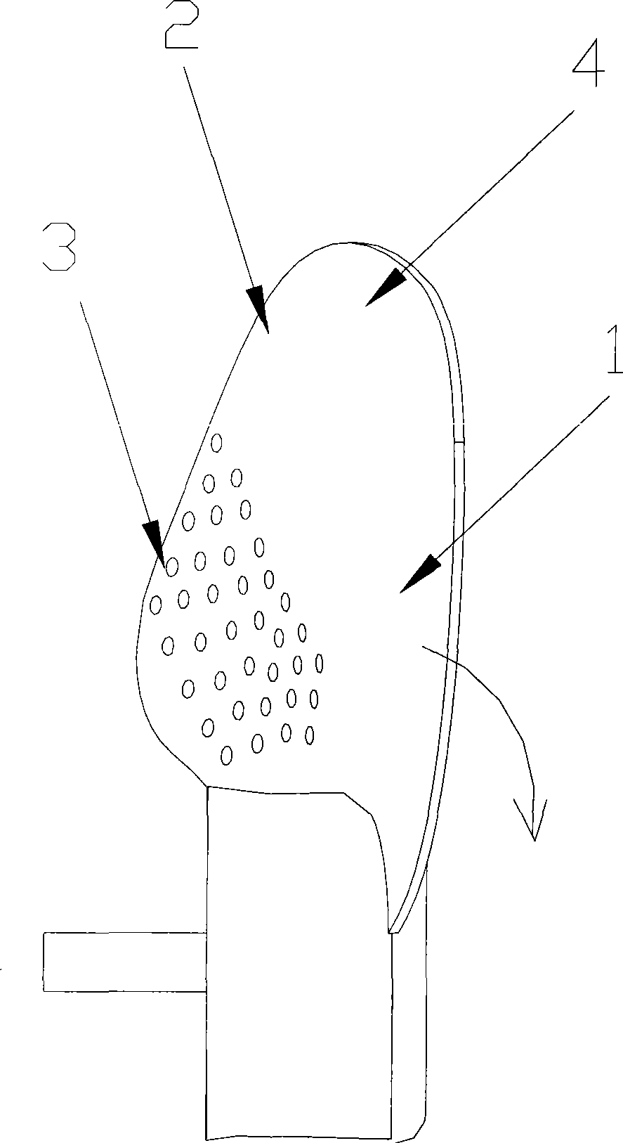
[0024] Embodiment 1: as figure 2 , image 3 As shown, the axial flow fan blade of the present invention includes a front edge portion 1 in the direction of air inflow and a rear edge portion 2 in the direction of air outflow. The rear edge portion 2 is provided with several pressure balance holes 3 . Several pressure balance holes 3 may be circular holes, non-circular holes, straight through holes, straight blind holes, oblique through holes or oblique blind holes. The distribution of several pressure balance holes 3 constitutes a hole network to regulate the pressure on both sides of the fan blade. The diameter range of the pressure balance hole 3 is 0.1mm-100mm.

[0025] It has been proved by experiments that there are several pressure balance holes 3 on the trailing edge 2, which play the role of self-balancing pressure, reduce the pressure difference between the front and back of the fan blade, and eliminate the boundary layer airflow separation zone of the trailing edg...

Embodiment 2

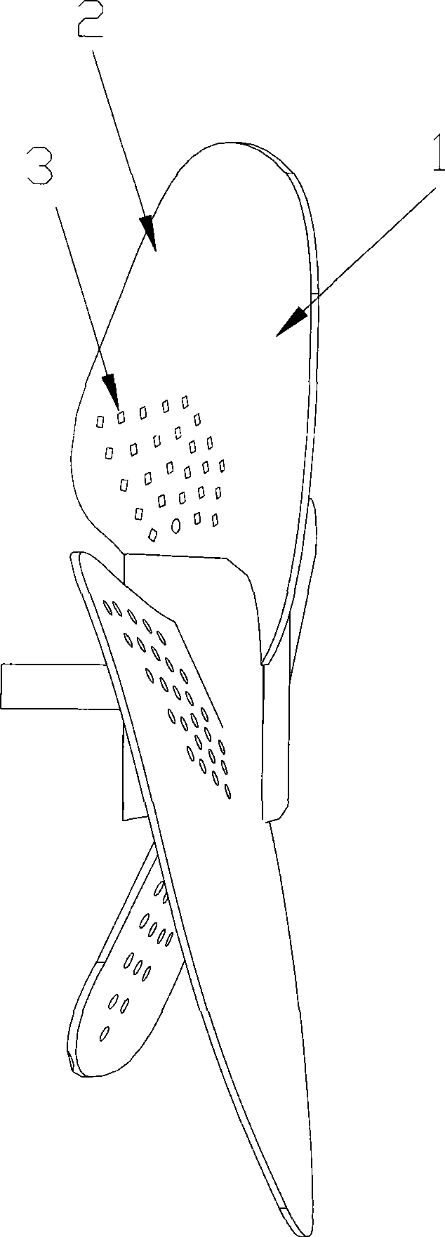
[0026] Embodiment 2: as Figure 4 , Figure 5 As shown, the centrifugal fan blade of the present invention includes a front edge portion 1 in the air inflow direction and a rear edge portion 2 in the air outflow direction, and several pressure balance holes 3 are opened on the rear edge portion 2 . Several pressure balance holes 3 may be circular holes, non-circular holes, straight through holes, straight blind holes, oblique through holes or oblique blind holes. The distribution of several pressure balance holes 3 constitutes a hole network to regulate the pressure on both sides of the fan blade. The diameter range of the pressure balance hole 3 is 0.1mm-100mm.

[0027] It has been proved by experiments that there are several pressure balance holes 3 on the trailing edge 2, which play the role of self-balancing pressure, reduce the pressure difference between the front and back of the fan blade, and eliminate the boundary layer airflow separation zone of the trailing edge 2...


PUM


Abstract

The invention relates to a fan blade of an axial fan or a centrifugal fan, which comprises a front edge part (1) in an air inflow direction and a back edge part (2) in an air outflow direction, and is characterized in that the back edge part (2) is provided with a plurality of pressure balancing holes (3). Because the back edge part of the fan blade is provided with the plurality of the pressure balancing holes, the fan blade reduces pressure difference between the front and the back of the fan blade, eliminates backflow phenomenon brought by air current separation at a boundary layer of the back edge part, and increases effective functional area of the fan blade, so as to potentially improve power consumption and noise quality, and avoid depositing large amount of dust at the same time.

Description

Technical field: [0001] The invention mainly relates to a fan blade of an axial flow fan and a fan blade of a centrifugal fan. Background technique: [0002] Such as figure 1 As shown, the blade of the existing axial flow fan has a front edge portion 1 in the direction of air inflow and a rear edge portion 2 in the direction of air outflow. The design of the edge part 2 is conducive to the outflow of air. Experiments have proved that: 1) when the fan blade rotates, the air flow at the rear edge of the fan blade is affected by the increased rotational kinetic energy, resulting in separation of the air flow in the boundary layer during the process of the air flow flowing out of the rear edge part 2 Bring backflow phenomenon, easy to deposit a large amount of dust 4 on the trailing edge part 2 of the windward side 3, see from the cooling axial flow fan on the computer in the experiment, we can easily find the situation described above. The windward side 2 of the wind blade re...

Claims


Application Information

Patent Timeline
Patent Type & Authority Applications(China)
IPC IPC(8): F04D29/30F04D29/38
CPCF04D29/30F04D29/281F04D29/681F04D29/289F04D29/682F04D29/684
Inventor 张达陈宇奇
Owner ZHONGSHAN BROAD OCEAN
Why Eureka
Try Eureka