Energy storage enthalpy increasing heat pump heat supply system

A heating system and heat pump technology, applied in heating systems, hot water central heating systems, heat pumps, etc., can solve problems such as easy frosting of the evaporator, failure of the heat pump to start, difficulty in starting, etc.

Active Publication Date: 2011-11-16
GAO XIUMING
View PDF1 Cites 0 Cited by
  • Summary
  • Abstract
  • Description
  • Claims
  • Application Information

AI Technical Summary

Problems solved by technology

[0002] The existing water loop heat pump system has been found to have the following shortcomings after long-term use: 1. When the existing air source-water loop heat pump system and water source-water loop heat pump system are in the heating state, when the side of the condensing heat exchanger is loaded with refrigerant (Heat medium water) It is difficult to start when the temperature is low; 2. During the start-up and operation of the existing air source-water loop heat pump system and water source-water loop heat pump system when the system is in the heating state, when the side load of the condensing heat exchanger When the temperature of the refrigerant (heat medium water) is low, the heating quality of the heat pump system is poor, that is, the outlet water temperature is low, which cannot reach the water temperature required by people, the equipment efficiency is low, and even the heat supply will drop significantly.
In addition, due to the low pressure of the evaporator, according to the thermal performance of the refrigerant, the evaporator is easy to frost. When the evaporator is frosted, the evaporator cannot exchange heat with the ambient air.
When the frosting reaches a certain level, the system will enter the defrosting process that only consumes energy without heating and consumes the heat energy of the output system, which exacerbates the difficulty of starting and running the heat pump system. After several cycles, the heat pump system It will be paralyzed, which is what the industry says, the problem that the heat pump cannot start at low temperature

Method used


Image

  • Energy storage enthalpy increasing heat pump heat supply system
  • Energy storage enthalpy increasing heat pump heat supply system

Examples


Embodiment Construction

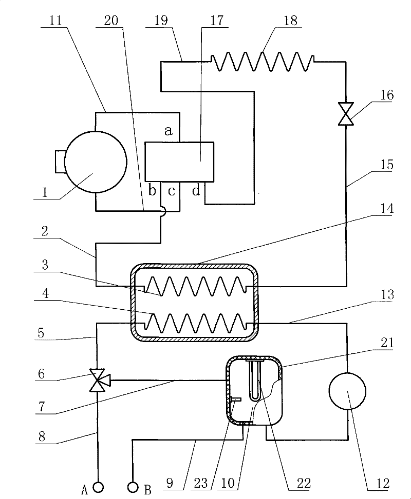
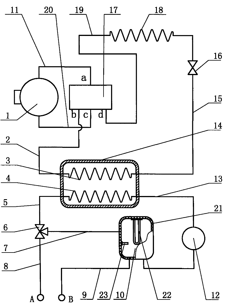
[0011]The energy storage enthalpy-increasing heat pump heating system of the present invention includes a refrigerant circulation system, a heat exchanger shell 14 is installed on the outer periphery of the first heat exchange coil 3 of the refrigerant circulation system, and a heat exchanger shell 14 is installed inside the heat exchanger shell 14. The second heat exchange coil 4, one end of the second heat exchange coil 4 is connected to one end of the first water pipe 5, the other end of the first water pipe 5 protrudes outside the heat exchanger shell 14 and is connected to the three-way valve 6, three The through valve 6 is connected with one end of the second water pipe 7, the other end of the second water pipe 7 is connected with the energy storage water tank 10, the energy storage water tank 10 is connected with one end of the fifth water pipe 13, and the other end of the fifth water pipe 13 is connected with the second water pipe 13. The other end of the heat exchange ...


PUM


Abstract

The present invention discloses a energy storage enthalpy increasing heat pump heat distribution system which comprises a refrigerant circulation system, wherein a first heat exchange coil thereof is positioned inside of a heat exchanger shell, the heat exchanger shell is provided with a second heat exchange coil, one end of the second heat exchange coil is connected with one end of a first waterpipe, the other end of the first water pipe extends out the heat exchanger shell and is connected with a three-way valve, the three-way valve is connected with one end of the second water pipe, the other end of the second water pipe is connected with an energy storage tank, the energy storage tank is connected with one end of a fifth water pipe, and the other end of the fifth water pipe is connected with the other end of the second heat exchange coil, the fifth water pipe is provided with a water pump, the three-way valve and the energy storage tank are respectively provided with a third water pipe and a fourth water pipe, the third water pipe and the fourth water pipe are connected with a heat radiator of a user terminal, and a temperature sensor is arranged inside the energy storage tank. The present invention can realize heat pump quick start and highly effective operating, improve the quality of hot water produced during the heat pump heat-production operating starting, greatly improve using efficiency of an heat pump system equipment and give heat pump system potential full play.

Description

technical field [0001] The invention relates to an energy storage enthalpy increasing heat pump heating system. Background technique [0002] The existing water loop heat pump system has been found to have the following shortcomings after long-term use: 1. When the existing air source-water loop heat pump system and water source-water loop heat pump system are in the heating state, when the side of the condensing heat exchanger is loaded with refrigerant (Heat medium water) It is difficult to start when the temperature is low; 2. During the start-up and operation of the existing air source-water loop heat pump system and water source-water loop heat pump system when the system is in the heating state, when the side load of the condensing heat exchanger When the temperature of the refrigerant (heat medium water) is low, the heating quality of the heat pump system is poor, that is, the outlet water temperature is low, which cannot reach the water temperature required by people...

Claims


Application Information

Patent Timeline
Patent Type & Authority Patents(China)
IPC IPC(8): F24D3/02F24D3/10F25B13/00F25B30/02
CPCY02P80/10
Inventor 高秀明
Owner GAO XIUMING
Why Eureka
Try Eureka