
Magnetic resonance imaging apparatus and magnetic resonance imaging method

A technology of magnetic resonance imaging and magnetic resonance data, applied in measuring devices, measuring magnetic variables, medical science, etc., can solve problems such as the difficulty in distinguishing blood flow, blood vessels and organs, and the inability to maintain a stable state of magnetization of flowing substances

Inactive Publication Date: 2009-05-27
TOSHIBA MEDICAL SYST CORP
View PDF1 Cites 14 Cited by
  • Summary
  • Abstract
  • Description
  • Claims
  • Application Information

AI Technical Summary

Problems solved by technology

[0033] However, the image obtained by the conventional SSFP time-series imaging is an image in which flowing substances such as blood flow are superimposed on organs
Therefore, when focusing only on blood flow and blood vessels, there is a problem that it may be difficult to distinguish blood flow, blood vessels, and organs due to the mixture of flowing substances and organs.
[0034] In addition, in the conventional SSFP sequence, there is also a problem that the magnetization of static substances such as organs is effectively maintained in a stable state, but if the control of the gradient magnetic field is insufficient, the magnetization of flowing substances may not be maintained in a stable state.

Method used


Image

  • Magnetic resonance imaging apparatus and magnetic resonance imaging method
  • Magnetic resonance imaging apparatus and magnetic resonance imaging method
  • Magnetic resonance imaging apparatus and magnetic resonance imaging method

Examples


Embodiment Construction

[0062] Embodiments of the magnetic resonance imaging apparatus and the magnetic resonance imaging method of the present invention will be described with reference to the drawings.

[0063] Figure 5 It is a configuration diagram showing an embodiment of the magnetic resonance imaging apparatus of the present invention.

[0064] The magnetic resonance imaging apparatus 20 is configured such that a cylindrical static magnetic field magnet 21 forming a static magnetic field, a shimming coil 22 provided inside the static magnetic field magnet 21, and a gradient magnetic field coil are built in an unillustrated gantry. 23 and RF coil 24.

[0065] The magnetic resonance imaging apparatus 20 includes a control system 25 . The control system 25 includes a static magnetic field power supply 26 , a gradient magnetic field power supply 27 , a shimming coil power supply 28 , a transmitter 29 , a receiver 30 , a timing controller 31 , and a computer 32 . The gradient magnetic field powe...


PUM


Abstract

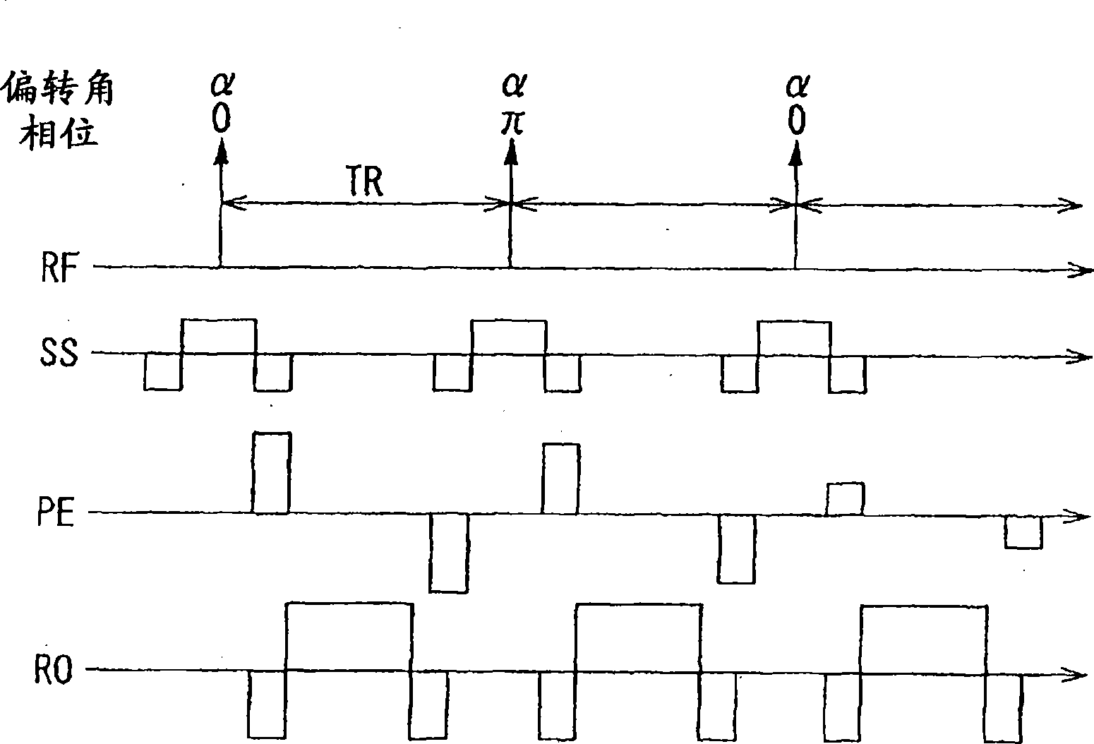
The present invention provides a magnetic resonance imaging apparatus and method. The magnetic resonance imaging apparatus comprises a data acquisition unit and an image generating unit. The data acquisition unit configured to acquire magnetic resonance data according to an imaging condition for obtaining a steady state free precession of nuclear magnetic spins in flowing matter in an object by applying plural excitation pulses having a same flip angle with a constant repetition time (TR) and gradient magnetic fields to the object; wherein respective zero order moments of gradient magnetic field within the repetition time (TR), gradient magnetic field for slice selection from each application time of the plural excitation pulses till a center time of a corresponding echo, gradient magnetic field for readout from each application time of the plural excitation pulses till a center time of a corresponding echo, gradient magnetic field for slice selection from a center time of each echo till an application time of a following excitation pulse, gradient magnetic field for readout from a center time of each echo till an application time of a following excitation pulse are zero while a first order moment of at least one of gradient magnetic field for slice selection and gradient magnetic field for readout within the repetition time is nonzero. The image generating unit is configured to generate an image of the flowing matter based on the magnetic resonance data.

Description

technical field [0001] The present invention relates to magnetically exciting the spins of atomic nuclei of a subject using a Larmor frequency (RF: Radio Frequency) signal, and reconstructing an image from a nuclear magnetic resonance (NMR: Nuclear Magnetic Resonance) signal accompanying the excitation. A magnetic resonance imaging (MRI: Magnetic Resonance Imaging) device and a magnetic resonance imaging method, in particular to a magnetic resonance imaging device and a magnetic resonance imaging method for obtaining a magnetic resonance image of a flowing substance by using steady state free precession (SSFP: Steady State FreePrecession) . Background technique [0002] Magnetic resonance imaging is an imaging method in which nuclear spins of a subject placed in a static magnetic field are magnetically excited by an RF signal of a Larmor frequency, and an image is reconstructed from an NMR signal accompanying the excitation. [0003] In this field of magnetic resonance imag...

Claims


Application Information

Patent Timeline
IPC IPC(8): G01R33/561A61B5/055
Inventor 油井正生
Owner TOSHIBA MEDICAL SYST CORP
Learn More