Multi-frequency antenna

A multi-frequency antenna and wire technology, which is applied to the antenna, the device that enables the antenna to work in different bands at the same time, the structural form of the radiation element, etc., can solve the problem of not being able to take into account high bandwidth at the same time

Inactive Publication Date: 2009-05-27
连展科技电子(昆山)有限公司
View PDF2 Cites 8 Cited by
  • Summary
  • Abstract
  • Description
  • Claims
  • Application Information

AI Technical Summary

Problems solved by technology

[0006] The purpose of the present invention is to provide a multi-frequency antenna, which uses the first radiating arm and the second radiating arm to excite the low-frequency resonance mode, and the parasitic conductor excites the high-frequency resonance mode, so that the integration of the antenna system covers a variety of operating frequency bands and has ultra-wideband characteristics, improving the miniaturization of known antennas can not take into account the lack of high bandwidth (bandwidth) at the same time

Method used


Image

  • Multi-frequency antenna
  • Multi-frequency antenna
  • Multi-frequency antenna

Examples


Embodiment Construction

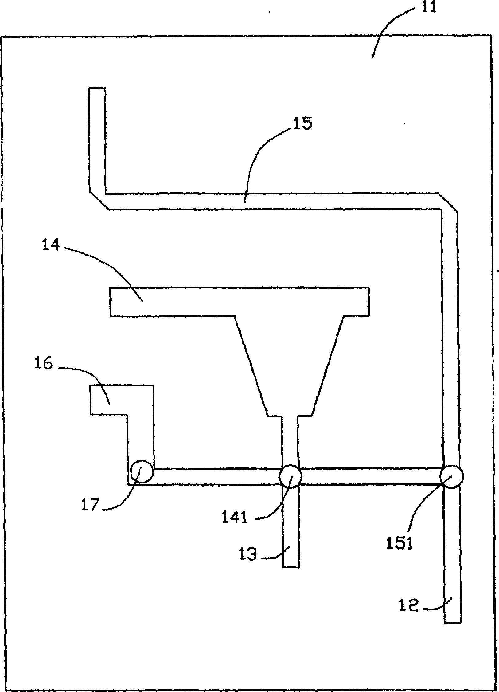
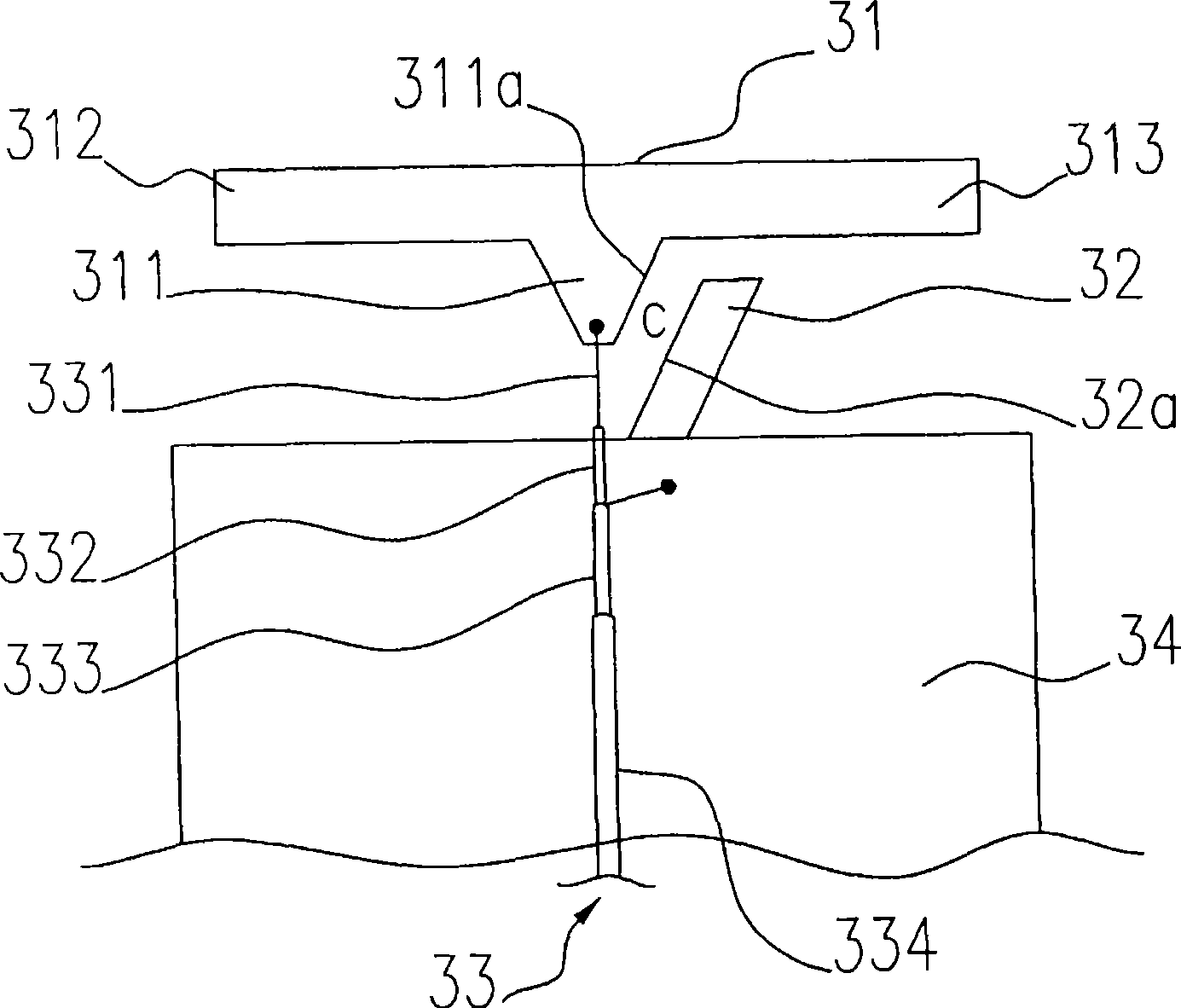
[0058] The multi-frequency antenna of the present invention includes: a ground plane, a radiation conductor, a parasitic conductor and a feed-in line. The radiation conductor includes: a feed-in part, a first radiation arm and a second radiation arm; the feed-in line includes: a central wire and an outer layer wire; the feed-in part has a first coupling side, and the first radiation arm is connected to the feed-in part along a certain One direction extends from the feed-in part, the second radiation arm is connected to the feed-in part and extends from the feed-in part in a direction opposite to the extending direction of the first radiation arm; the parasitic conductor is connected to the ground plane, has a second coupling side and extends along the The outline of the first coupling side of the feed-in part is configured, and a gap is formed between the second coupling side of the parasitic conductor and the first coupling side of the feed-in part; the central wire is connect...


PUM


Abstract

The invention relates to a multi-frequency antenna, which comprises a ground plane, a radiation conductor, a parasitic conductor and a feed-in wire, wherein the radiation conductor comprises a feed-in part, a first radiation arm and a second radiation arm; the feed-in wire comprises a central wire and an external wire; the feed-in part is provided with a coupling edge; the parasitic conductor is connected with the ground plane and provided with a coupling edge which is arranged along a profile of the coupling edge of the feed-in part, and a gap is formed between the coupling edge of the parasitic conductor and the coupling edge of the feed-in part; the central wire is connected with the feed-in part; and the external wire is connected with the ground plane. The low-frequency resonance mode is excited through the first radiation arm and the second radiation arm and the high-frequency resonance mode is excited through the parasitic conductor, so that an antenna system integrally covers various operation frequency bands and has the characteristic of ultra wide band; and simultaneously the composition structure of the antenna is simplified.

Description

technical field [0001] The invention relates to a multi-frequency antenna, in particular to an antenna system that integrates and covers ultra-wideband technical characteristics. Background technique [0002] With the advent of the wireless communication era, antenna products with light weight, small size, good reception, and low cost will become the mainstream of the market. Dual-band antennas are miniaturized antennas. Two resonant frequencies are produced. The known dual-frequency antenna is usually a combination of two or more different antenna types. For example, the dual-frequency antenna structure disclosed in U.S. Patent No. 6,204,819 combines a planar inverted-F antenna and a loop antenna. Select different signal feed-in methods to switch between the two antennas. However, the antenna is a three-dimensional structure, which is bulky and difficult to configure. In addition, a switching chip must be added to operate the frequency band switching, resulting in a comple...

Claims


Application Information

Patent Timeline
IPC IPC(8): H01Q1/36H01Q1/38H01Q5/00H01Q13/08H01Q5/10H01Q5/20H01Q5/378
Inventor 曾义伟林圣智邱宗文萧富仁
Owner 连展科技电子(昆山)有限公司
Why Eureka
Try Eureka