
Single-effect evaporator

A kind of efficient evaporation and combined technology, applied in the direction of vertical tube evaporator, etc., can solve the problems of low actual productivity, short equipment life, insufficient heating of materials, etc.

Active Publication Date: 2010-09-15
沈阳东方钛业股份有限公司
View PDF0 Cites 0 Cited by
  • Summary
  • Abstract
  • Description
  • Claims
  • Application Information

AI Technical Summary

Problems solved by technology

[0002] Prior to this, the first-effect evaporator was mainly imported from abroad, with high cost and short equipment life; the heat exchange tube was fixed inside the shell only by the tube-side tube plate and the shell-side tube plate, and there was no fixing bracket for the heat exchange tube, so the fixation was not firm ;The connection between the heat exchange tube and the tube sheet is strength welding, and the pull-off force is low; the material flow distribution in the tube side of the equipment is uneven, resulting in insufficient heating of the material, large energy consumption, low actual productivity, and high production cost

Method used


Image

  • Single-effect evaporator
  • Single-effect evaporator
  • Single-effect evaporator

Examples


Embodiment Construction

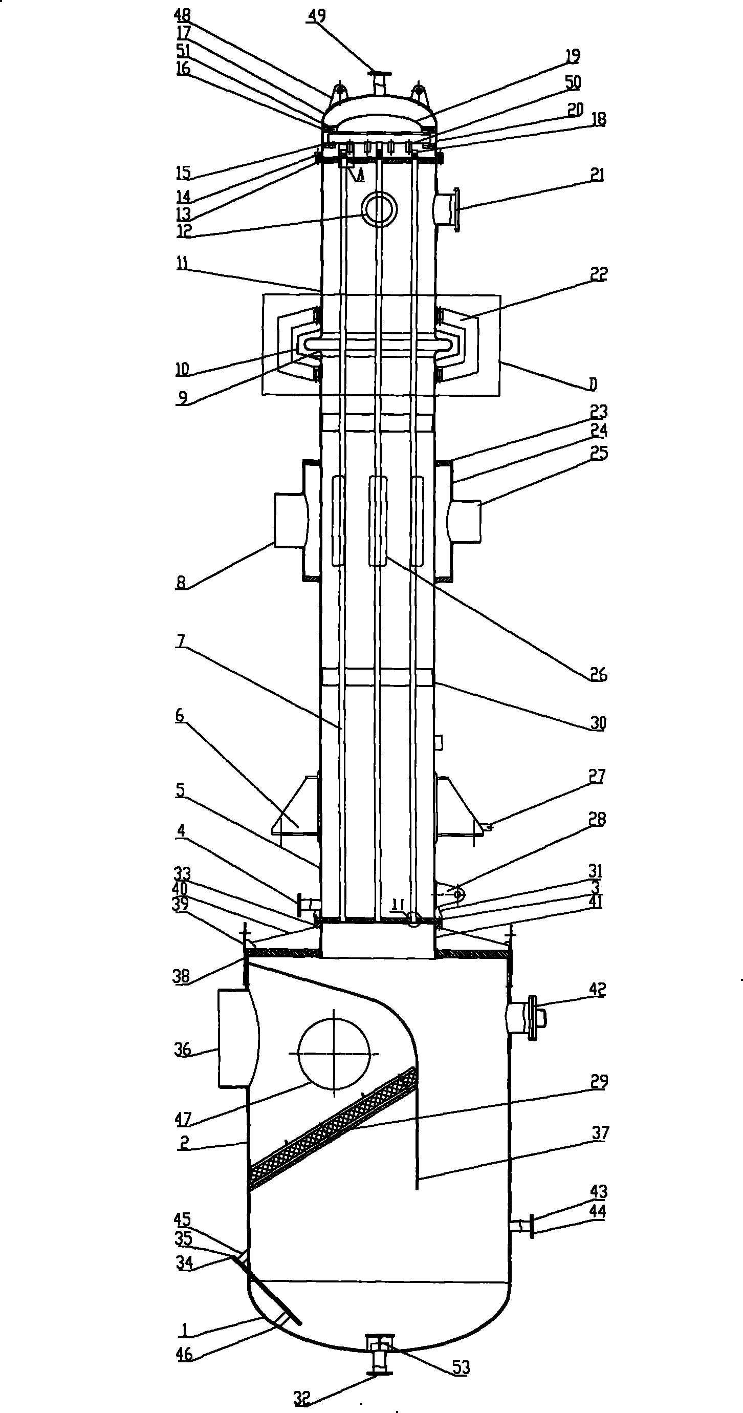
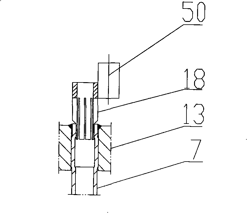
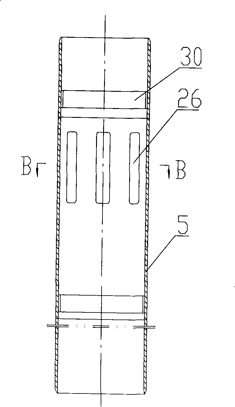
[0030] Such as Figure 1 to Figure 10 As shown, a one-effect evaporator consists of two parts, the tube side and the shell side.

[0031] The tube pass is: the tube pass head 1 is connected to the tube pass cylinder body 2, and the tube pass cylinder body 2 and the tube pass nipple 41 are connected together through the tube pass upper cover 38, the rib plate 40 and the side wall ear 39; The lye outlet 32 ​​and the anti-eddy current baffle 53 are arranged on the process head 1, and the instrument gauge intubation 34 and the liquid level gauge intubation 35 are connected to the tube-side cylinder 2 and the tube-side head 1 through ribs 45, 46. Together; on the tube side cylinder body 2, there are hand openings 42, steam outlets 36, manhole openings 47, liquid level gauge ports 43 and liquid level gauge alarm ports 44, and the tube side cylinder body 2 is provided with a wire mesh defoamer Device 29 and baffle plate 37, one end of baffle plate 37 is connected with tube pass shel...


PUM


Abstract

The invention relates to a single-effect evaporator. The technical proposal is that the single-effect evaporator comprises a tube pass and a shell pass. A cylinder body of the tube pass, a sealing end of the tube pass and an upper cover of the tube pass constitute the tube pass, an alkaline liquid outlet, an anti-swirl baffle, a meter inserting tube, a liquid level meter inserting tube, a steam outlet and a liquid level meter alarm port are arranged on the tube pass, a wire mesh demister and a baffle are arranged in the tube pass; an expansion joint which is sleeved with a protective cover ofthe expansion joint and a protective support connects the upper and the lower cylinder bodies of the shell pass, and the two ends of a short joint of the shell pass are connected with the upper cylinder body of the shell pass and the sealing end of the shell pass; the sealing end of the shell pass is provided with an alkaline liquid inlet; the short joint of the shell pass is provided with a distributing cover, a receiving plate, a distributing plate and a downcomer; the steam inlet is connected with the lower cylinder body of the shell pass through a shell body and the annular plate; the lower cylinder body of the shell pass is provided with a condensate outlet; a tube supporting frame is arranged in the lower cylinder body of the shell pass; the short joint of the tube pass is connectedwith the lower cylinder body of the shell pass; a tube plate is provided with a heat exchange tube hole, a heat exchange tube penetrates the two ends of the tube supporting frame to be connected withthe tube plate, and one end thereof is connected with a distributing tube. The single-effect evaporator improves the stability and the pull-out force of the heat exchange tube and reduces the energy consumption and the production cost.

Description

Technical field: [0001] The invention relates to a one-effect evaporator device used for circulation heating of lye, especially a one-effect evaporator device for realizing transformation of low-temperature and low-concentration lye into high-temperature and high-concentration lye. Background technique: [0002] Prior to this, the first-effect evaporator was mainly imported from abroad, with high cost and short equipment life; the heat exchange tube was fixed inside the shell only by the tube-side tube plate and the shell-side tube plate, and there was no fixing bracket for the heat exchange tube, so the fixation was not firm The connection between the heat exchange tube and the tube sheet is strength welding, and the pull-off force is low; the material flow distribution in the tube side of the equipment is uneven, resulting in insufficient heating of the material, large energy consumption, low actual productivity, and high production cost. Invention content: [0003] In o...

Claims


Application Information

Patent Timeline
Patent Type & Authority Patents(China)
IPC IPC(8): B01D1/06
Inventor 梁显军董志贵孔庆堂李军
Owner 沈阳东方钛业股份有限公司
Learn More