Wind generator system

A technology for wind power generation systems and generators, applied in wind power generator components, wind power generation, wind power engines, etc., can solve the problems of high wind energy utilization rate, excessive blade diameter, difficult cost, etc., and achieve high wind energy utilization rate and low cost The effect of reducing the wind area and facilitating transportation

Inactive Publication Date: 2009-06-03
刘运科
View PDF0 Cites 17 Cited by
  • Summary
  • Abstract
  • Description
  • Claims
  • Application Information

AI Technical Summary

Problems solved by technology

[0004] The purpose of the present invention is to overcome the disadvantages of the large and medium-sized horizontal axis generator wind rotor blade diameter is too large under the existing technical conditions, so that the design, manufacture, transportation, installation, maintenance and other aspects of blades, towers and other parts The problem of cumbersome and difficult work and high cost is solved, providing a convenient manufacturing, installation and maintenance, wide application range, and can greatly reduce the diameter and overall size of the current large wind turbine rotor blades, low cost, wind energy High Utilization Coaxial Multistage Wind Wheel Horizontal Axis Wind Turbine

Method used


Image

  • Wind generator system
  • Wind generator system
  • Wind generator system

Examples


Embodiment 1

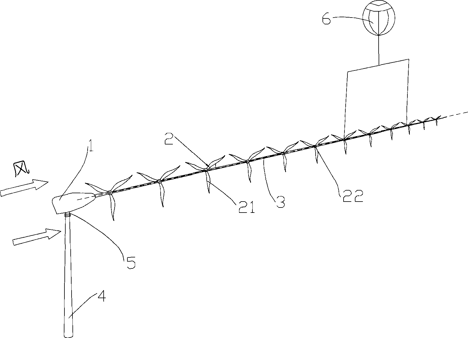
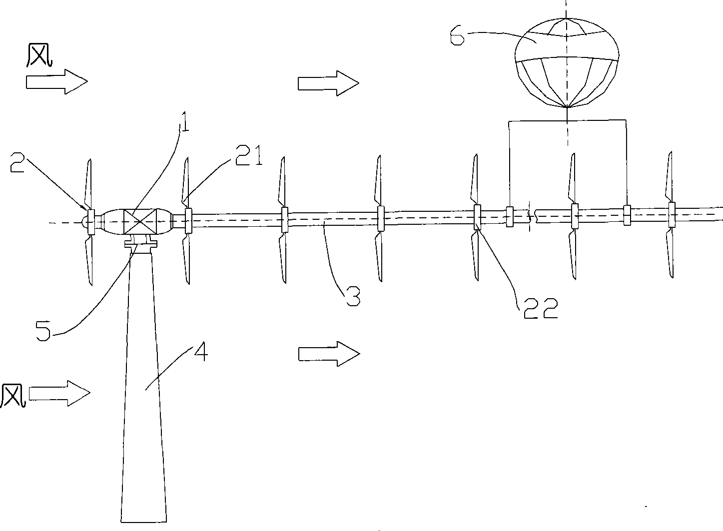
[0033] see figure 1 , figure 2As shown, a wind power generation system includes a tower 4, a generator assembly 1 arranged on the tower 4, and a transmission shaft 3 connected to the generator assembly 1, and the movement along the axial direction of the transmission shaft 3 is kept at intervals. A multistage wind wheel 2 is installed. The generator assembly 1 is installed on the tower 4 through the direction adjustment device 5, so that the axial direction of the transmission shaft 3 can be adjusted according to the wind direction, so that the rotating surface of the wind wheel 2 faces the flow direction of the wind at any time.

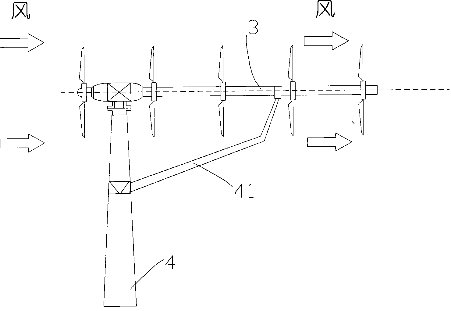
[0034] When the transmission shaft 3 is longer and the number of stages of the wind wheel 2 is more, the tail end of the transmission shaft 3 can be equipped with a balloon floating system 6 . see image 3 As shown, when the transmission shaft 3 is shorter and the number of stages of the wind wheel 2 is less, a support bracket 41 can be provided...

Embodiment 2

[0045] see Figure 9 As shown, the difference from the first embodiment is that the elastic coupling mechanism 24 of this embodiment is arranged outside the transmission shaft section 35, which includes a fixed plate 36, a tension spring or a compression spring 241 arranged on the corresponding transmission shaft section 35, One end of the tension spring or compression spring 241 is connected to the fixing plate 36 , and the other end is connected to the hub 22 of the wind wheel 2 on the transmission shaft section 35 .

Embodiment 3

[0047] see Figure 12 As shown, different from the above-mentioned embodiments, this embodiment does not use the elastic coupling mechanism 24, but sets the shaft tube sheath 34 as a bellows with telescopic elasticity, and the two ends of the shaft tube sheath 34 are respectively connected to the corresponding The hub 22 of the adjacent wind wheel 2 is connected. At this time, the shaft tube sheath can not only protect the transmission shaft, but also elastically constrain the adjacent wind rotors, so that the adjacent wind rotors will not collide with each other due to the blowing of the wind, which further simplifies the structure of the present invention.


PUM


Abstract

The invention discloses a wind generator system which comprises a tower, a generator assembly which is arranged on the tower, a transmission shaft which is connected with the generator assembly, and multi-stage wind wheels which are movably arranged and spaced along the axial direction of the transmission shaft. The multi-stage wind wheels with small blades are arranged on the same shaft to replace a single wind wheel with huge blades, thus overcoming various disadvantages which are caused by huge blades of the existing huge wind generator, enhancing wind energy utilization efficiency, and universality and economical efficiency of the application of the wind electric power generation. In addition, for the generators with the same power, decrease of diameter of the wind wheels causes corresponding increase of rotation speed of the wind wheels so that transmission ratio of a gear box is reduced, manufacturing and installation cost of the gear box is reduced, which can further enhance economical efficiency of the generator system. The system has the advantages of low cost, high wind energy utilization ratio, convenient and easy manufacture, installation and maintenance, wide application field range, and can greatly reduce the diameter and whole size of the wind wheels of the existing big and small wind generators to facilitate transportation.

Description

technical field [0001] The invention relates to the technical field of wind power generation, in particular to a wind power generation system. Background technique [0002] Wind energy is a kind of non-polluting renewable energy. It is inexhaustible and widely distributed. With the requirements of environmental protection and the need for clean energy, the development and utilization of wind energy has been paid more and more attention by people. Power generation is the main way to utilize wind energy on a large scale. [0003] The horizontal axis wind turbine is currently the most common and successfully applied form of wind turbine, and its main component for utilizing wind energy is the blade of the wind rotor (installed on the hub). With the advancement of technology, the output power of the designed and manufactured wind generators also increases, so the diameter of the installed wind rotors becomes larger and larger. Today, the installed wind turbines in the world ha...

Claims


Application Information

Patent Timeline
Patent Type & Authority Applications(China)
IPC IPC(8): F03D9/00F03D1/06F03D1/04F03D11/00F03D9/25F03D13/20
CPCY02E10/722Y02E10/72Y02E10/721Y02P70/50
Inventor 刘运科
Owner 刘运科
Why Eureka
Try Eureka