LED road lamp and illuminating light-regulating method therefor

一种LED路灯、调整方法的技术,应用在光源、电光源、反射器等方向,能够解决光照射面不均匀、照明角度小等问题,达到照射均匀、亮度增大、最佳照明效果的效果

Inactive Publication Date: 2009-06-03
ZHEJIANG JINGRI LIGHTING TECH
View PDF0 Cites 19 Cited by
  • Summary
  • Abstract
  • Description
  • Claims
  • Application Information

AI Technical Summary

Problems solved by technology

However, LED street lights also have shortcomings, that is, the lighting angle is too small and the light irradiation surface is uneven.

Method used


Image

  • LED road lamp and illuminating light-regulating method therefor
  • LED road lamp and illuminating light-regulating method therefor
  • LED road lamp and illuminating light-regulating method therefor

Examples


Embodiment 1

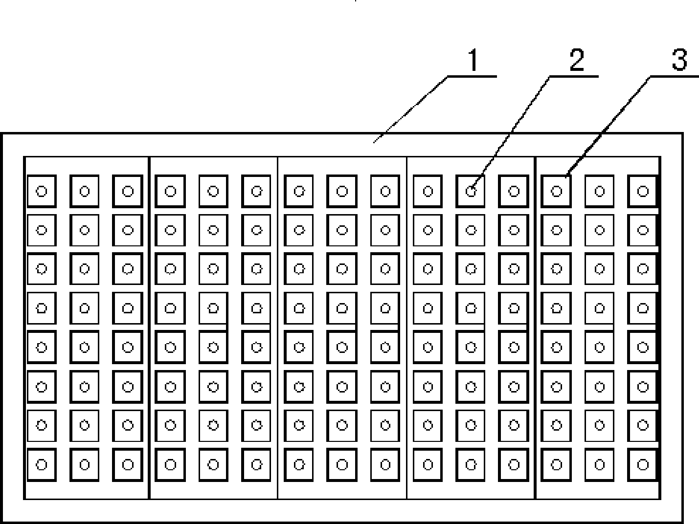
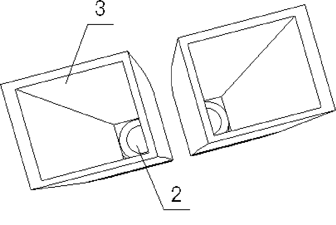
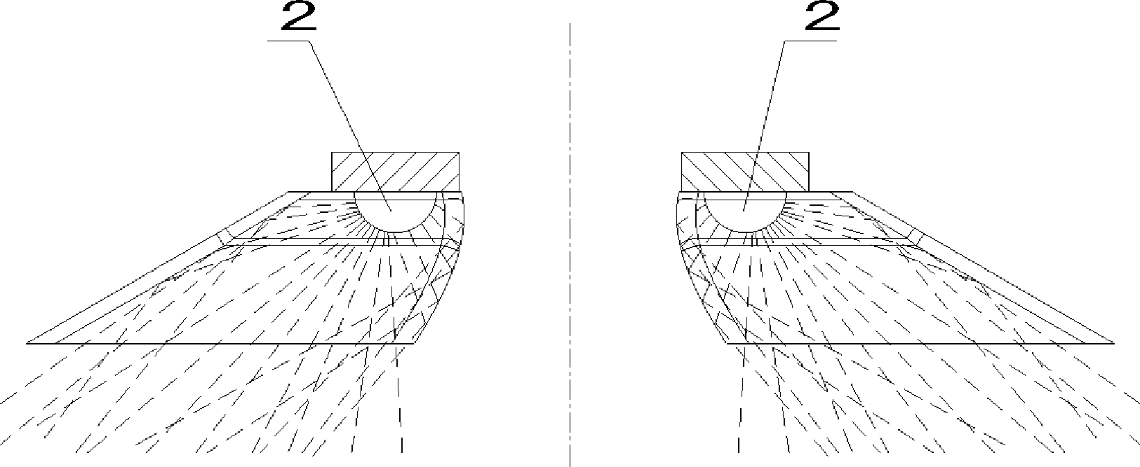
[0018] Example 1. as attached figure 1 As shown, it includes a lamp body 1 and LED luminous tubes 2 , and a reflector 3 is installed on each LED luminous tube 2 . Wherein the structure of reflective cup 3 is as attached figure 2 As shown, it is a quadrangular conical shell structure with a narrow top and a wide bottom. The top surface has no cover, the bottom surface is rectangular, and the bottom opening is inclined 30 degrees to the left or right. The LED light-emitting tube 2 is installed on the top surface of the reflector 3. The length direction of the rectangular bottom surface of the reflector 3 extends along the road surface, and the reflected light overlaps with the road surface. In practical applications, according to the needs of use, multiple sets of reflective cups with the bottom opening tilted 30 degrees to the left and the bottom surface tilted 30 degrees to the right can be installed in the same lamp body at the same time, so that the scattered light emitte...

Embodiment 2

[0019] Example 2. It includes a lamp body 1 and LED luminous tubes 2 , and a reflector 3 is installed on each LED luminous tube 2 . Wherein the reflective cup 3 is a quadrangular conical shell structure with a narrow top and a wide bottom, with no cover on the top surface and an opening on the bottom surface inclined 60 degrees to the left or right. In practical applications, according to the needs of use, multiple sets of reflective cups with the bottom opening tilted 60 degrees to the left and the bottom surface tilted 60 degrees to the right can be installed in the same lamp body at the same time, so that the scattered light emitted by the luminous tube 2 can be concentrated and projected at the same time after being reflected. On the road on the left side of the street lamp and the right side of the street lamp, it is also possible to install only multiple sets of reflector cups with the bottom opening inclined 60 degrees to the left in the same lamp body, or only install ...

Embodiment 3

[0020] Example 3. It includes a lamp body 1 and LED luminous tubes 2 , and a reflector 3 is installed on each LED luminous tube 2 . Wherein the reflective cup 3 is a quadrangular conical shell structure with a narrow top and a wide bottom, with no cover on the top surface and an opening on the bottom surface inclined 15 degrees to the left or right. In practical applications, according to the needs of use, multiple sets of reflective cups with the bottom opening tilted 15 degrees to the left and the bottom surface tilted 15 degrees to the right can be installed in the same lamp body at the same time, so that the scattered light emitted by the luminous tube 2 can be concentrated and projected at the same time after being reflected. On the road on the left side of the street lamp and the right side of the street lamp, it is also possible to install only multiple sets of reflector cups with the bottom opening tilted 15 degrees to the left in the same lamp body, or only install mu...


PUM


Abstract

The invention discloses an LED road lamp and an illuminating light-regulating method therefor. The LED road lamp comprises a lamp body (1) and an LED luminescent tube (2). A light-reflecting cup (3) is arranged on the LED luminescent tube (2). The light emergent from the LED luminescent tube is reflected by the light-reflecting cup and then focused to the road surface in need of illumination. The LED road lamp has optimum light intensity distribution, thereby broadening the illumination range and increasing the illumination brightness, providing LED light uniformly to light the road surface uniformly, meeting the requirements for road lighting, reducing glare to improve the safety of driving on the road at the same time, and overcoming the problem of light waste in the 'bright-under-lamp' phenomenon of the prior light source.

Description

technical field [0001] The invention relates to a structure of an LED street lamp and a method for adjusting the irradiation light of the LED street lamp. Background technique [0002] LED street lamps have been widely used due to their high luminous efficiency, energy saving (nearly 80% power saving), no need for high voltage, and high safety. Their performance has now surpassed that of commonly used fluorescent lamps. In addition to saving energy, LED street lights also have a much longer service life than traditional light bulbs (up to 80,000 hours or more), and because they do not use mercury, mercury, lead and other harmful substances commonly found in ordinary light bulbs, LED street lights are also more environmentally friendly. However, there are also shortcomings in LED street lights, that is, the lighting angle is small and the light irradiation surface is uneven. Contents of the invention [0003] The technical problem to be solved by the present invention is t...

Claims


Application Information

Patent Timeline
Patent Type & Authority Applications(China)
IPC IPC(8): F21V7/04F21W131/103F21Y101/02
CPCF21V17/164F21V7/09F21Y2105/001F21V7/0083F21Y2101/02F21W2131/103Y02B20/72F21V7/04F21Y2105/10F21Y2115/10F21S8/085
Inventor 程世友
Owner ZHEJIANG JINGRI LIGHTING TECH
Why Eureka
Try Eureka