Coupling structure and coupling method for coupling piping of air contitioner

A technology for connecting structures and air conditioners, applied in air conditioning systems, sealing surface connections, pipes/pipe joints/fittings, etc., can solve the problems of refrigerant leakage, corrosion, poor air tightness, etc. Durability, leak prevention effect

Inactive Publication Date: 2009-06-03
SAMSUNG ELECTRONICS CO LTD
0 Cites 19 Cited by

AI-Extracted Technical Summary

Problems solved by technology

[0007] However, in order to save the manufacturing cost of the product, for example, when aluminum is used, if the connection structure as described above is used, the bell mouth processing part and the contact part cannot be firmly connected, so the airtightness is poor, resulting in refrigerant leakage.
[0008] And, ...

Abstract

The present invention discloses a coupling structure and a coupling method for a coupling piping of an air conditioner, capable of stably coupling a coupling piping made of cheap material such as aluminum metal. The invention includes a coupling piping, one end of which is connected with an outdoor unit and the other end is connected to an indoor unit, to guide refrigerant; a combination member, for combining the coupling piping and the outdoor unit as well as the indoor unit. Moreover, a metallic loop for preventing the refrigerant from leakage is inserted between piping connection portions of at least one of the coupling piping and the outdoor unit as well as the indoor unit, and consolidation is implemented by the combination member.

Application Domain

Technology Topic

Image

  • Coupling structure and coupling method for coupling piping of air contitioner
  • Coupling structure and coupling method for coupling piping of air contitioner
  • Coupling structure and coupling method for coupling piping of air contitioner

Examples

  • Experimental program(1)

Example Embodiment

[0039] Hereinafter, the connection structure of the connecting pipe for the air conditioner provided by the preferred embodiment of the present invention will be described in detail with reference to the accompanying drawings.
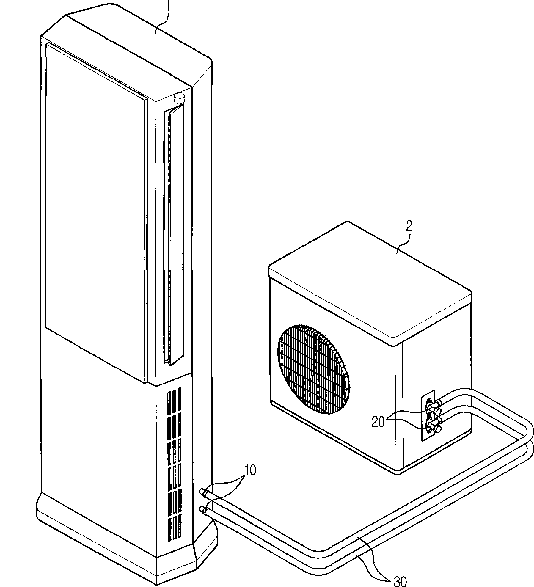
[0040] figure 1 It is a perspective view of the air conditioner provided by the present invention.
[0041] Such as figure 1 As shown, the air conditioner provided by the present invention includes: an indoor unit 1 installed in a room where air needs to be conditioned; an outdoor unit 2 installed outside the air-conditioned space; a connecting pipe 30 connecting the outdoor unit 2 and the indoor unit 1 to Used to circulate the refrigerant between the indoor unit 1 and the outdoor unit 2.
[0042] Although not shown, the indoor unit 1 includes: a heat exchanger; and an exhaust fan that provides exhaust air for supplying heat-exchanged air to the room. The outdoor unit 2 includes a compressor, a capillary tube, a heat exchanger, and an exhaust fan. This is the same structure as a general existing air conditioner, so its description is omitted.
[0043] The indoor unit 1 and the outdoor unit 2 are provided with piping connection parts 10 and 20 for the inflow and outflow of refrigerant. The piping connection parts 10 and 20 may be: nipples 10 installed in the indoor unit 1 and used to flow the refrigerant from the outdoor unit 2 to the indoor unit 1 or to flow the refrigerant from the indoor unit 1 to the outdoor unit 2 , And a maintenance valve 20 installed in the outdoor unit 2 and used to flow the refrigerant from the indoor unit 1 side to the outdoor unit 2 or to flow the refrigerant from the outdoor unit 2 to the indoor unit 1 side.
[0044] figure 2 This is a perspective view of the main part of the connection structure of the connecting pipe for the air conditioner provided by the first embodiment of the present invention, image 3 To represent figure 2 A cross-sectional view of the connected state of the connecting piping.
[0045] Such piping connection parts 10 and 20 are made of aluminum material in order to save manufacturing cost.
[0046] In order to enlarge the contact area with the connection pipe 30, inclined parts 10a, 20a are formed in the end part of the pipe connection part 10, 20. In addition, on the outer peripheries of the pipe connection portions 10 and 20, external thread portions 10b and 20b for coupling with the coupling member 50, which will be described later, are formed.
[0047] The connecting pipe 30 is made of aluminum material like the pipe connecting parts 10 and 20 in order to save manufacturing cost, and a bell mouth processing part 31 is formed at the end.
[0048] In this way, if the pipe connection portions 10, 20 and the connection pipe 30 formed of aluminum material use the connection structure of the connection pipe provided by the prior art, the connection is not strong enough, which may cause refrigerant leakage.
[0049] Therefore, in the present invention, a metal ring 40 is inserted between the inner surface 31a of the bell mouth processing portion 31 of the connecting pipe 30 and the outer surface of the inclined portions 10a, 20a of the pipe connecting portions 10, 20 to prevent refrigerant leakage and improve durability.
[0050] The metal ring 40 can preferably be made of copper metal or copper alloy, and can also be made of a metal having ductility and ductility similar to copper metal.
[0051] The coupling member 50 made of the same material as the connection pipe 30 and the pipe connection parts 10 and 20 is used to connect the connection pipe 30 and the pipe connection parts 10 and 20. In addition, since the coupling member 50 is inserted into the connection pipe 30 and the bell mouth processing portion 31 is formed at both ends of the connection pipe 30, the coupling member 50 does not separate from the connection pipe 30 and is slidable relative to the connection pipe 30.
[0052] One side of the inside of the coupling member 50 is formed with an inclined surface 52 similar to the inclination of the bell mouth processing portion 31 so as to be supported on the outer surface 31b of the bell mouth processing portion 31, and the other side is formed with the piping connection portions 10, 20 The female screw part 51 corresponding to the male screw part 10b, 20b is used for coupling with the pipe connection part 10, 20.
[0053] The connection of the connecting pipe for an air conditioner of the present invention uses the above-mentioned structure to insert the metal ring 40 between the bell mouth processing portion 31 and the inclined portions 10a, 20a of the pipe connection portion 10, 20, and then connect the connection member 50 and the pipe connection portion 10, 20 Make threaded connections.
[0054] At this time, the metal ring 40 and the bell mouth processing portion 31 and the metal ring 40 and the inclined portions 10a, 20a are maintained tightly according to the bonding force of the connecting member 50 and the pipe connection portions 10 and 20, and the bell mouth processing portion is also maintained The outer surface 31b of 31 and the inclined surface 52 of the coupling member 50 are firmly coupled, so that damage to the bell mouth processing portion 31 or refrigerant leakage due to damage to the bell mouth processing portion 31 can be prevented.
[0055] In addition, since the metal ring 40 is formed of a metal different from the coupling member 50, the pipe connection portions 10, 20, and the connection pipe 30, if air or moisture penetrates into the coupling portion, galvanic corrosion may occur and cause damage.
[0056] In order to prevent this phenomenon, the sealant 60 is injected between the coupling member 50 and the connecting pipe 30 and between the coupling member 50 and the pipe connection portions 10 and 20 so that foreign matter cannot flow into the metal ring 40 side.
[0057] As an example of the sealant 60, a piping sealant manufactured by Loctite, USA, or a sealant capable of exhibiting similar performance may be used.
[0058] Therefore, in the present invention, when the existing piping and piping connection parts made of copper metal are made of other metal materials that can save manufacturing cost, and then they are combined, insert a different metal material from the piping and piping connection parts The metal ring can prevent refrigerant leakage and breakage of the bell mouth processing part, and the sealant prevents foreign substances from flowing into the metal ring side, so it can prevent corrosion and improve durability.
[0059] Hereinafter, the connection structure of the connecting pipe for the air conditioner provided by the second embodiment of the present invention will be described.
[0060] The same structure as the first embodiment of the present invention is given the same reference numeral, and the description thereof is omitted.
[0061] Figure 4 This is a perspective view of the main part of the connection structure of the connecting pipe for the air conditioner provided by the second embodiment of the present invention, Figure 5 To represent Figure 4 A cross-sectional view of the connected state of the connecting pipes.
[0062] The second embodiment uses the same material and structure as the first embodiment of the present invention to configure the connecting pipe 70 and the pipe connecting portions 10', 20'. In addition, a metal ring 40 is inserted between the connection pipe 70 and the pipe connection portions 10 ′ and 20 ′ and joined by the coupling member 50 ′, and then the sealant 60 prevents foreign substances from flowing into the metal ring 40 side.
[0063] At this time, unlike the first embodiment, the connecting pipe 70 does not form a bell mouth processing part. In order to enlarge the contact area of ​​the connecting pipe 70 and the pipe connecting portions 10', 20' without the flare processing part, the thickness t2 of the connecting pipe 70 of the second embodiment is thicker than that of the connecting pipe 30 of the first embodiment. It has a thickness t1 and forms a first inclined portion 71 that is recessed toward the center of the connecting pipe 70. In addition, the outer circumference of the connecting pipe 70 is formed with an external thread portion 72 for coupling with the coupling member 50'.
[0064] The piping connection portions 10', 20' correspond to the first slanted portion 71 and form second slanted portions 10a', 20a', and are formed to support the coupling member 50' in order to connect the connection pipe 70 with the piping connection portions 10', 20'的卡台11, 21.
[0065] One side of the inner surface of the coupling member 50' corresponds to the external thread portion 72 of the connecting pipe 70 to form an internal thread portion 51', and the other side corresponds to the chuck 11, 21 of the pipe connection portion 10', 20' to form a clamping portion 52'.
[0066] For the connection of the connecting pipe for air conditioner, the metal ring 40 is inserted between the first inclined portion 71 of the connecting pipe 70 and the second inclined portion 10a', 20a' of the pipe connecting portion 10', 20' and the connecting member 50' is threadedly connected with the connecting pipe 70.
[0067] After that, the sealant 60 is injected between the coupling member 50' and the connecting pipe 70 and between the coupling member 50' and the pipe connection portions 10' and 20' so that foreign matter cannot flow into the metal ring 40 side.
[0068] This coupling structure of connecting pipes can achieve the same effect as the first embodiment.
[0069] Hereinafter, the connection structure of the connecting pipe for the air conditioner provided by the third embodiment of the present invention will be described.
[0070] The same structure as the second embodiment of the present invention is assigned the same reference numeral, and the description thereof is omitted.
[0071] Figure 6 This is a perspective view of the main part of the connection structure of the connecting pipe for the air conditioner provided by the third embodiment of the present invention, Figure 7 To represent Figure 6 A cross-sectional view of the connected state of the connecting pipes.
[0072] The third embodiment uses the same material and structure as the first embodiment of the present invention to form the connection pipe 70 and the pipe connection portions 10 ″, 20 ″. In addition, a metal ring 40 is inserted between the connection pipe 70 and the pipe connection portions 10 ′ ′ and 20 ′ ′, and is coupled by the coupling member 50 ′ ′, and then the sealant 60 prevents foreign substances from flowing into the metal ring 40 side.
[0073] At this time, the connecting pipe 70 has the same structure as that of the second embodiment, so its description is omitted.
[0074] The piping connection portions 10 ″, 20 ″ correspond to the first slanted portion 71 to form second slanted portions 10 a ″, 20 a ″, and the outer peripheries of the piping connection portions 10 ″, 20 ″ are formed for coupling with the member 50 ''Connected external threaded parts 12, 22.
[0075] One side of the inner surface of the coupling member 50′′ corresponds to the external thread 72 of the connecting pipe 70 to form a first internal thread 51′′, and the other side corresponds to the external thread 12 of the piping connection part 10′′ and 20′′. 22 to form a second internal threaded portion 52''. The thread directions of the first and second internal threaded portions 51" and 52" are opposite, so that if the coupling member 50" is rotated in one direction, the pipe connection portions 10", 20" and the connecting pipe 70 are mutually Approaching, and turning in the other direction, the piping connection portions 10' and 20' and the connection piping 70 will move away from each other.
[0076] The connection of the connecting pipe for the air conditioner has the above-mentioned structure, and a metal ring is inserted between the first inclined portion 71 of the connecting pipe 70 and the second inclined portion 10a′′, 20a′′ of the pipe connecting parts 10′′, 20′′ 40 and threadedly connect the coupling member 50' with the connecting pipe 70 and the pipe connecting parts 10' and 20'.
[0077] After that, the sealant 60 is injected between the coupling member 50 ′ ′ and the connection pipe 70 and between the coupling member 50 ′ ′ and the pipe connection portions 10 ′ ′, 20 ′ ′ so that foreign matter cannot flow into the metal ring 40 side.
[0078] This coupling structure of connecting pipes can achieve the same effect as the first embodiment.
[0079] In the connection structure of the connecting pipe for the air conditioner provided by the present invention, the first, second, and third embodiments can be used to connect the screw interface of the indoor unit and the connection pipe, and the connection of the maintenance valve of the outdoor unit and the connection pipe, respectively. In use, of course, the connection between the connection pipe and the threaded interface and the connection between the connection pipe and the maintenance valve can be independently used in different embodiments.

PUM

no PUM

Description & Claims & Application Information

We can also present the details of the Description, Claims and Application information to help users get a comprehensive understanding of the technical details of the patent, such as background art, summary of invention, brief description of drawings, description of embodiments, and other original content. On the other hand, users can also determine the specific scope of protection of the technology through the list of claims; as well as understand the changes in the life cycle of the technology with the presentation of the patent timeline. Login to view more.

Similar technology patents

Classification and recommendation of technical efficacy words

  • Avoid Galvanic Corrosion
  • Prevent leakage

Bipolar plate for flow batteries

ActiveCN103474673AAvoid Galvanic CorrosionExtended service lifeCell electrodesEngineeringElectrochemical corrosion
Owner:DALIAN RONGKE POWER

Bonding method of PDLC films for vehicles

InactiveCN108274731AExtended service lifeAvoid Galvanic CorrosionNon-linear opticsLiquid crystalEngineering
Owner:GUANGZHOU HUAHUI MATERIAL TECH CO LTD

Blast furnace gas washing deacidification apparatus and method thereof

Owner:秦皇岛双轮环保科技股份有限公司

Energy-saving water heater with adjustable heating rate

InactiveCN108006951AAdjust heating timeAvoid Galvanic CorrosionWater heatersHeating timeEngineering
Owner:DONGGUAN LIANZHOU INTPROP OPERATION MANAGEMENT CO LTD

Apparatus and method for endoscopic colectomy

ActiveUS7338505B2Prevent leakagePerform more quickly and more safelySuture equipmentsEndoscopesColon wallSurgical department
Owner:INTUITIVE SURGICAL OPERATIONS INC
Why Eureka
Try Eureka