
Method and server for determining through optical path and system for establishing through optical path

A server and optical path technology, applied in the field of communications, can solve problems such as large service bandwidth, heavy router node burden, network congestion, etc., to optimize network resources, effectively utilize optical layer network resources, and reduce burdens.

Active Publication Date: 2009-06-03
HUAWEI TECH CO LTD
View PDF0 Cites 27 Cited by
  • Summary
  • Abstract
  • Description
  • Claims
  • Application Information

AI Technical Summary

Problems solved by technology

It can be seen that this static configuration method cannot dynamically adjust the network topology and optimize network resources
For example, two routers on the path, or called nodes, sometimes the service bandwidth between the two nodes is large, and sometimes the service bandwidth between the two nodes is small, if the direct optical path passing through the two nodes is not pre-configured, Then when the bandwidth between these two nodes is too large, it will cause network congestion
That is to say, since the two endpoints that need to establish a direct optical path cannot be dynamically determined, the network topology cannot be dynamically adjusted, so the optical layer network resources cannot be well used, and the burden on the nodes at the router level will be too large
[0005] It can be seen that the current method of determining the direct optical path cannot dynamically determine the two endpoints that need to establish the direct optical path, and at the same time, cannot dynamically adjust the network topology

Method used


Image

  • Method and server for determining through optical path and system for establishing through optical path
  • Method and server for determining through optical path and system for establishing through optical path
  • Method and server for determining through optical path and system for establishing through optical path

Examples


Embodiment Construction

[0026] In order to make the objectives, technical solutions, and advantages of the present invention clearer, the present invention will be further described in detail below with reference to the accompanying drawings and embodiments.

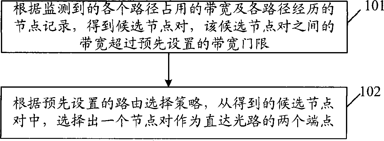
[0027] figure 1 It is a schematic flow chart of a method for determining a direct optical path adopted in an embodiment of the present invention. Such as figure 1 As shown, it includes the following steps:

[0028] Step 101: Obtain at least one candidate node pair according to the monitored bandwidth occupied by each path and the node record experienced by each path, and the bandwidth between these candidate node pairs exceeds a preset bandwidth threshold.

[0029] In this step, the method of monitoring the bandwidth occupied by each path includes: counting the path traffic within a set time, and dividing the path traffic by the set time to obtain the path within the set time Occupied bandwidth.

[0030] The method for obtaining the candidate no...


PUM


Abstract

The embodiment of the invention discloses a method for determining the through optical path, comprising the steps as follows: candidate node pairs are gained according to the bandwidth occupied by all monitored paths and router nodes which all paths go through; the bandwidth between the candidate node pairs exceeds the prearranged bandwidth threshold; according to the prearranged route selection strategy, one node pair is selected out of the candidate node pairs and used as two ends of the through optical path. The embodiment of the invention also discloses a server for determining the through optical path. The embodiment of the invention also discloses a system for establishing the optical path. The method, the server and the system can dynamically adjust the network topology and optimize the network resource.

Description

Technical field [0001] The present invention relates to the field of communications, in particular to a method and server for determining a direct optical path and a system for establishing a direct optical path. Background technique [0002] With the rapid development of broadband Internet, the scale of the network continues to expand, the network structure is becoming increasingly complex, network services are becoming more abundant, and network traffic is growing rapidly. Telecom operators need to use reliable and effective network service traffic monitoring systems to conduct timely and accurate traffic and flow analysis on the network and the various services carried by the network, so as to tap the potential of network resources, control network interconnection costs, and provide network planning, Optimizing adjustment and business development to provide a basic basis. [0003] The traffic monitoring data obtained by the above-mentioned network service traffic monitoring sy...

Claims


Application Information

Patent Timeline
Patent Type & Authority Applications(China)
IPC IPC(8): H04L12/56H04L12/26H04L29/12
CPCH04J14/0241H04L45/70H04Q2011/0064H04L45/62H04J14/0227H04Q2011/0073H04L45/125H04L45/64H04Q11/0062H04L45/12H04J14/0284H04L45/50H04J14/0257H04J14/0258H04J14/0267H04J14/0269H04J14/0271
Inventor 郑远明何健飞夏洪淼刘庆智李启铭徐慧颖
Owner HUAWEI TECH CO LTD
Learn More