Manufacturing method of display device

A manufacturing method and technology of a display device, which are applied in nonlinear optics, instruments, optics, etc., can solve the problems of time required, inability to equalize cell gaps, less redundant area, etc., and achieve the effect of good use efficiency

Inactive Publication Date: 2009-06-03
SHIN ETSU ENG
View PDF1 Cites 2 Cited by
  • Summary
  • Abstract
  • Description
  • Claims
  • Application Information

AI Technical Summary

Problems solved by technology

[0005] However, in such a conventional method of manufacturing a display device, the space for arranging dummy seals in which the main seal is ring-sealed at a constant interval between the substrates around the main seal can only be secured. parts, so there are problems in that the vacuum area is insufficient to reliably equalize the unit cell gap, and at the same time, the compressive force caused by atmospheric pressure is insufficient when using high-viscosity main seals or dummy seals. can't crush for sure
[0006] In addition, there is also a problem that since it is necessary to separate the closed space surrounded by the dummy seal in a ring form from th

Method used


Image

  • Manufacturing method of display device
  • Manufacturing method of display device
  • Manufacturing method of display device

Examples


Embodiment 1

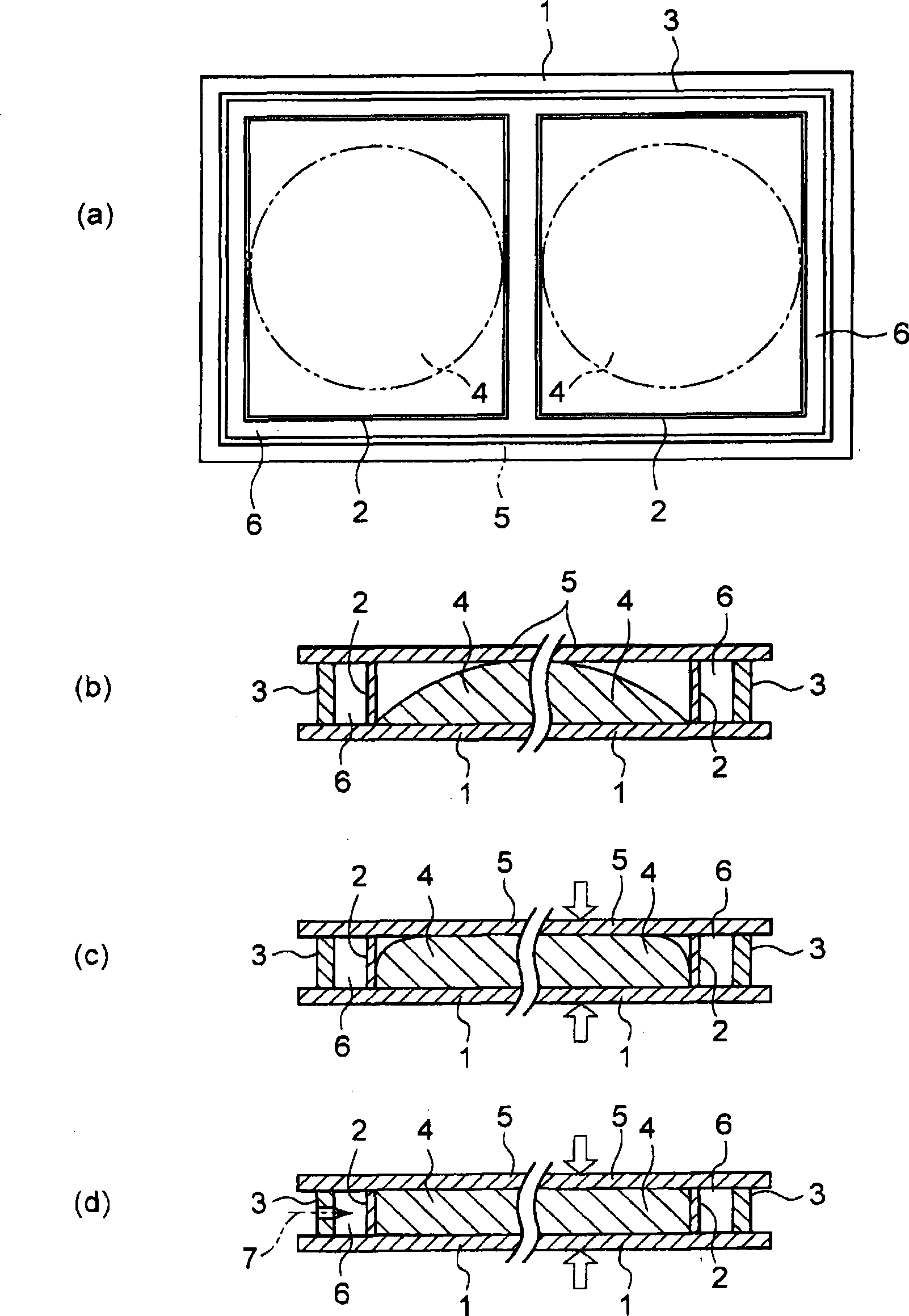
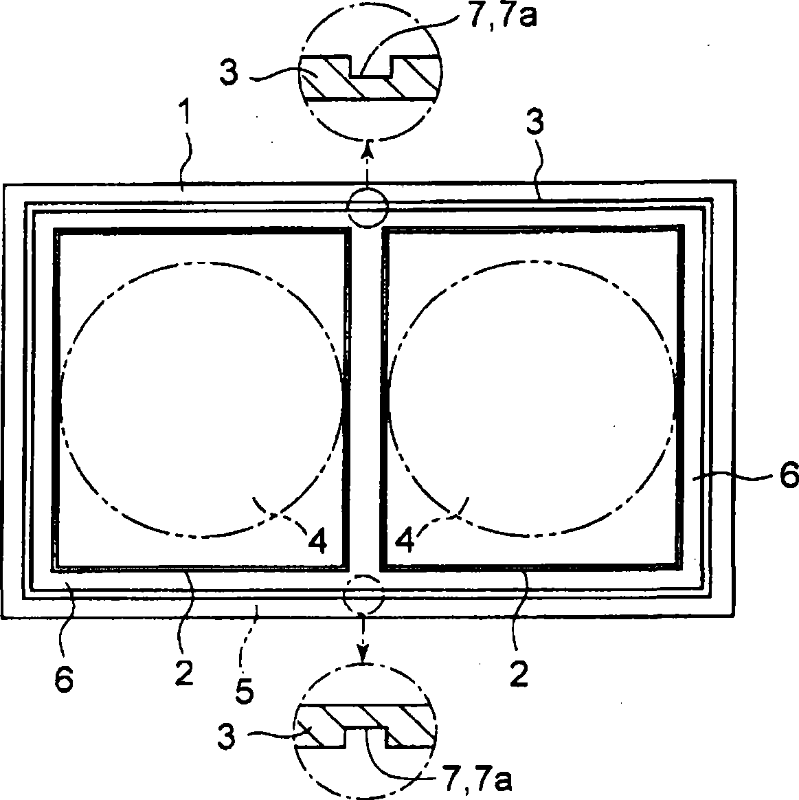
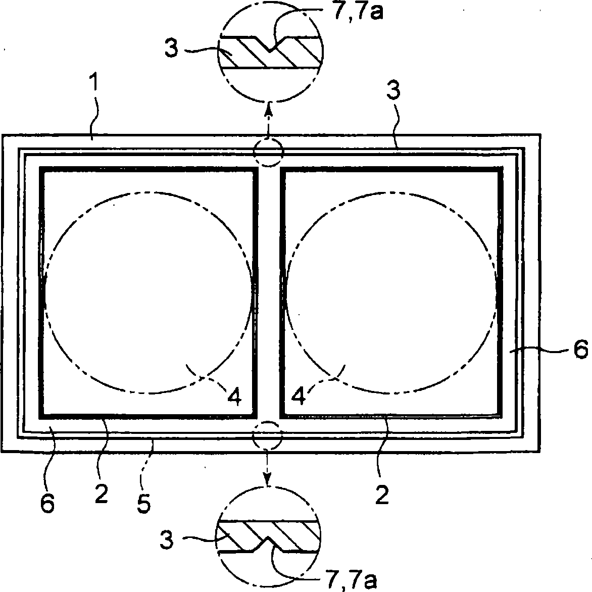
[0047] This Example 1, such as Figure 2 ~ Figure 6 As shown, after the pressure regulating valve mechanism 7 releases the atmospheric pressure to the set time, the safety part 7a is ruptured to simulate the pressure difference between the inside and outside of the sealing member 3, as any one of the substrates 1, for example, along the outer periphery of the lower substrate. The dummy seal 3 is formed into a ring shape (frame shape) by printing or coating, and one or more main seals 2 are arranged inside the dummy seal 3, and at the same time, on the outer periphery and Either or both of the inner circumferences are partially formed with only one securing portion 7a having a width narrower than the seal line of the dummy seal 3, or a plurality of them are formed at appropriate intervals.

[0048] The strength of the above-mentioned insurance part 7a is set such that the air outside the dummy seal 3 erodes the insurance part 7a, the width of the seal line becomes thinner gradu...

Embodiment 2

[0060] This Example 2, as in Figure 7 ~ Figure 14 As shown, the pressure regulating valve mechanism 7 is a small passage 7b with a small flow rate. Along the outer circumference of any one of the substrates 1 and 5, the dummy seal 3 is formed into a ring shape (frame shape) by printing or coating. ), and at the same time, only one small passage 7b passing through the inside and outside of the dummy seal 3 is partially formed at an appropriate place, or a plurality of passages 7b are formed at appropriate intervals. Such a configuration is different from the above-mentioned Figure 1 to Figure 6 shown in Example 1, while additionally constituted with Figure 1 to Figure 6 Example 1 shown is the same.

[0061] The small flow rate of the above-mentioned small passage 7b is set to fully have the following function: that is, when the atmosphere is released after the two substrates 1, 5 are vacuum bonded, the air outside the simulated sealing member 3 enters. At this time, the ga...


PUM


Abstract

The invention provides a manufacturing method of a display device. In the method, clearance is formed due to atmospheric pressure to save space, thus ensuring depressurization area and improving the resistance of a main sealing element. When two substrates (1, 5) are jointed, as the clearance forming space (6) is depressurized by a pressure regulating valve mechanism (7) in vacuum, the two substrates (1, 5) are compressed at the atmospheric pressure and equalize the unit cell clearance, and a packaging material (4) diffuses and extends along with the two substrates; an extension end of the packaging material (4) reaches the inside surface of the main sealing element (2) after the set time for opening the atmospheric pressure is over, and the extension pressure works, meanwhile, the atmospheric pressure is introduced into a vacuum part of the clearance forming space (6) and converted into the atmospheric pressure or a state similar to the atmospheric pressure by the pressure regulating valve mechanism (7), thus the atmospheric pressure or the state similar to the atmospheric pressure obtain pressure balance with the extension pressure of the packaging material (4), and the main sealing element (2) does not break.

Description

technical field [0001] The present invention relates to a method of manufacturing a display device in which a sealing material such as liquid crystal is sealed between a pair of substrates such as a liquid crystal display (LCD) or a liquid crystal panel, for example, using a drop casting method. [0002] More specifically, it relates to a method of manufacturing a display device, in which a main seal closed in a ring shape and a dummy seal surrounding its periphery are formed on one substrate, an encapsulating material is injected inside the main seal, and the The other substrate is nearly overlapped on it in vacuum and then returns to atmospheric pressure to simulate the pressure difference between the inside and outside of the seal to equalize the gap between the unit cells, and at the same time, make the packaging material spread and seal. Background technique [0003] Conventionally, as a method of manufacturing such a display device, a plurality of ring-shaped (frame-sh...

Claims


Application Information

Patent Timeline
IPC IPC(8): G02F1/1339
CPCG02F1/133351G02F1/1339
Inventor 横田道也
Owner SHIN ETSU ENG
Why Eureka
Try Eureka