
Self-oscillation starting output end controlled anti exciting converter

A flyback converter, self-excited oscillation technology, applied in output power conversion devices, control/regulation systems, conversion of DC power input to DC power output, etc., can solve the problem of reducing product life and reliability, low efficiency, control loop bandwidth limitation and other issues to achieve the effect of reducing no-load loss, high performance, and high reliability power supply

Inactive Publication Date: 2009-06-10
MORNSUN GUANGZHOU SCI & TECH
View PDF0 Cites 18 Cited by
  • Summary
  • Abstract
  • Description
  • Claims
  • Application Information

AI Technical Summary

Problems solved by technology

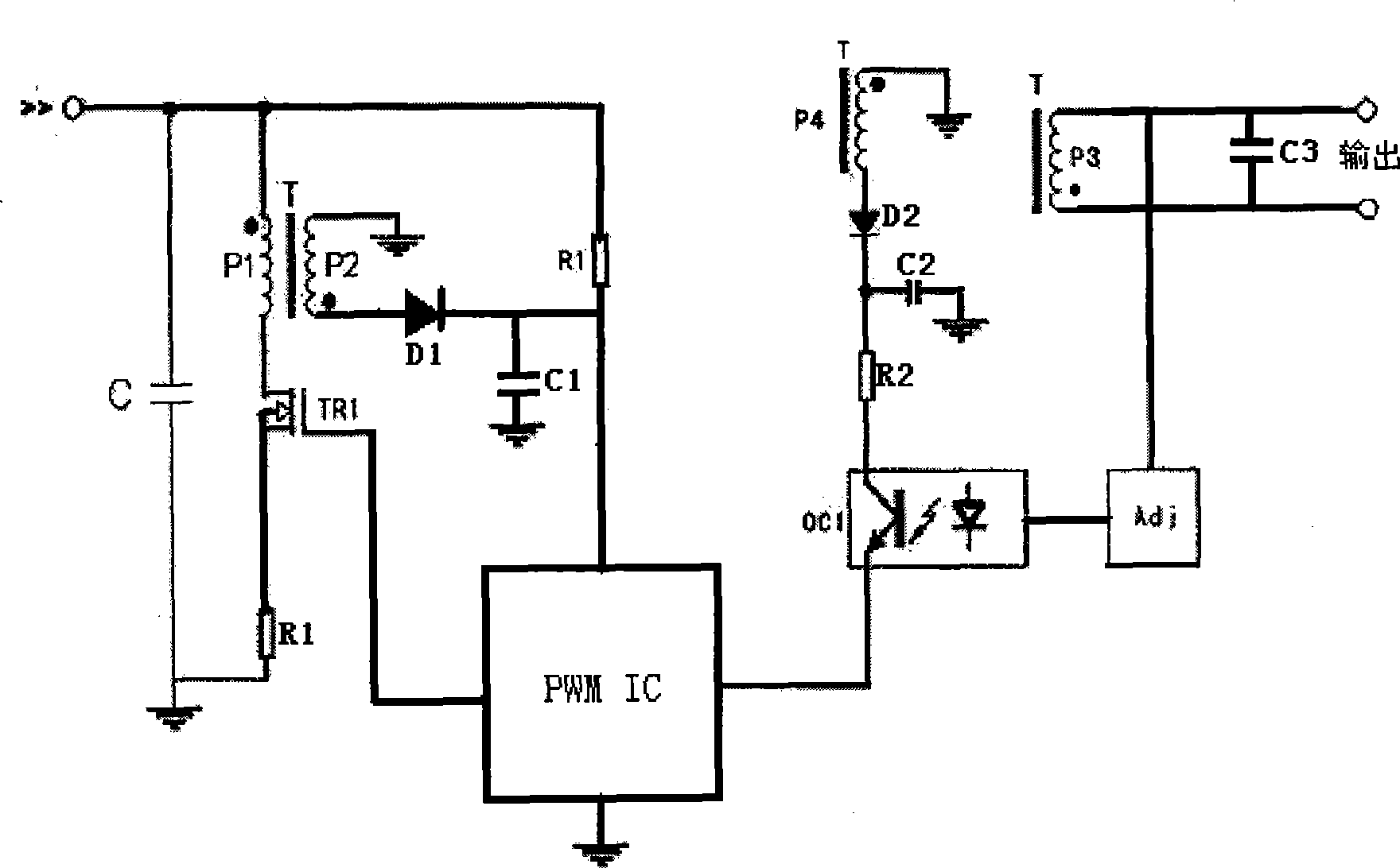
[0007] The self-excited oscillating flyback converter circuit of the first scheme, that is, the RCC circuit has a simple structure and low cost, but there are certain problems in the reliability of the product when it is relatively high-power and mass-produced, and the efficiency is low when it is light-loaded; Due to the presence of linear optocouplers in the two schemes, the bandwidth of the control loop is limited, and the life and reliability of the product are greatly reduced.

Method used


Image

  • Self-oscillation starting output end controlled anti exciting converter
  • Self-oscillation starting output end controlled anti exciting converter
  • Self-oscillation starting output end controlled anti exciting converter

Examples


Embodiment Construction

[0035] The flyback converter with self-power supply control at the output terminal according to the present invention will be further described below in conjunction with specific embodiments.

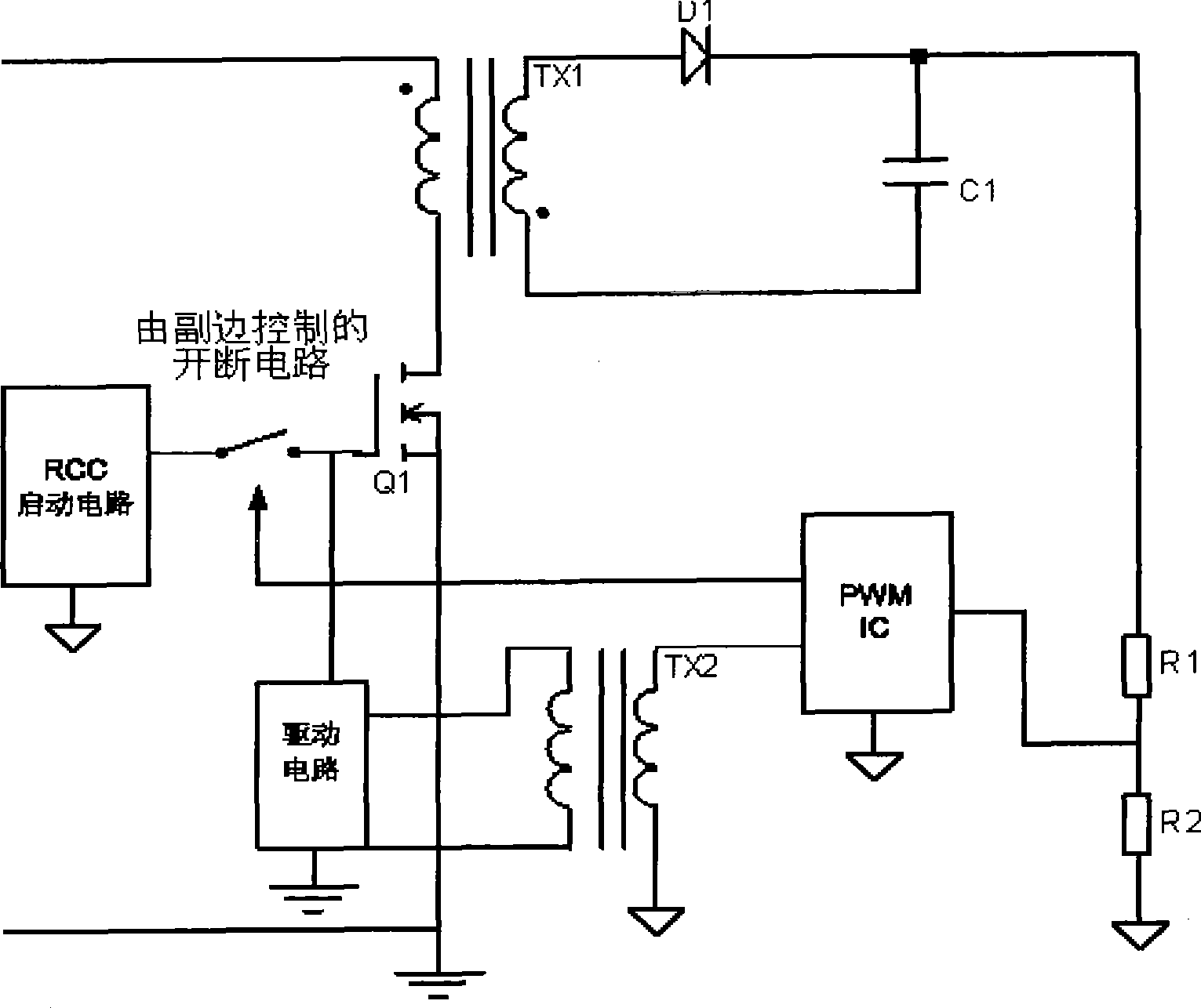
[0036] image 3 The principle structure diagram of a self-powered control flyback converter at the output is shown, including the flyback power conversion main circuit, the start-up oscillation circuit in the RCC circuit for starting the flyback power conversion main circuit, and the start-up oscillation circuit for disconnecting Circuit breaker, PWM control circuit for controlling flyback oscillation; flyback power conversion main circuit is mainly composed of MOS main switch tube Q1 and main oscillation transformer TX1; the output of the start-up oscillation circuit is connected to the flyback power conversion main In the circuit, the gate of the MOS main switch tube and the breaking device are connected to the main loop of the start-up oscillation circuit. The output of the flyback p...


PUM


Abstract

The invention discloses a flyback convertor controlled by a self-oscillation start output end, which comprises a flyback power conversion main circuit, a start oscillation circuit, a cut-off device and a PWM control circuit. The start oscillation circuit is connected with an MOS main switch tube grid in the flyback power conversion main circuit, and the cut-off device is connected in a return circuit of the start oscillation circuit. The PWM control circuit outputs two paths of signals, one path of trigger signal is connected to the cut-off control end of the cut-off device for controlling the cut-off of the start oscillation circuit, and the other path of PWM drive signal is connected to the MOS main switch tube grid in the flyback power conversion main circuit. The invention has the following characteristics that the flyback convertor does not need an extra auxiliary power supply to supply power to the PWM control circuit, easily realizes the control mode of synchronous rectification, and also easily realizes various protective circuits, and additional functions such as parallel current equalization, and so on; and the band width of a control loop is not limited to make the dynamic performance of the circuit better.

Description

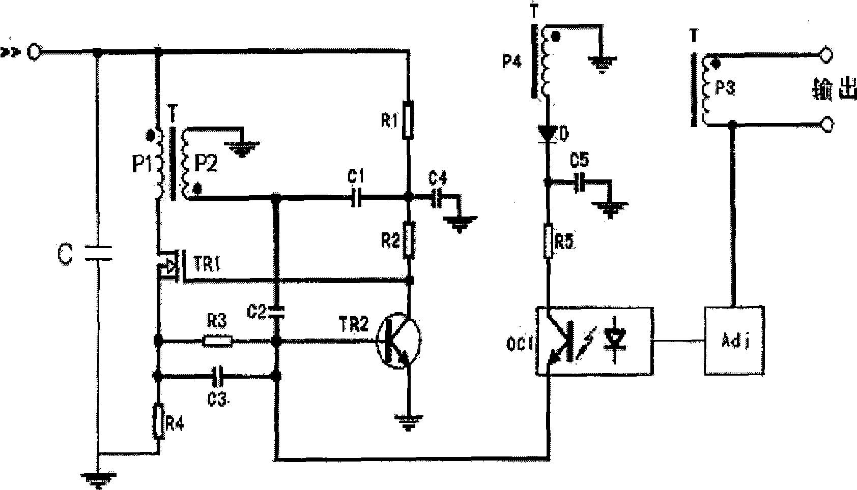
technical field [0001] The invention relates to a flyback converter, in particular to a flyback converter controlled by a self-excited oscillation starting output terminal. Background technique [0002] At present, there are various forms of self-oscillating flyback converters (that is, RCC circuits) in the industry. Commonly used RCC circuits such as figure 1 As shown, it is generally composed of the main current circuit part, the start-up oscillation circuit part, the negative feedback control voltage circuit part and the regulated output circuit part. Among them, the start-up oscillation circuit part is mainly composed of triode TR2, resistors R1, R2, R1, R2 and capacitors C2 and C3; the negative feedback control voltage loop part is composed of voltage regulator Adj and optocoupler OC1. [0003] The specific working principle is: when the input voltage is applied, the input voltage is applied to the gate of the MOS transistor TR1 through the resistors R1 and R2, so that...

Claims


Application Information

Patent Timeline
Patent Type & Authority Applications(China)
IPC IPC(8): H02M3/335H02M3/338
Inventor 尹向阳
Owner MORNSUN GUANGZHOU SCI & TECH
Learn More