
Receiving equipment, MMIS interface and data interaction method

A receiving device and interface technology, applied in the field of data transmission, can solve the problems of increasing the chip area and the number of pins, increasing the cost input, etc.

Inactive Publication Date: 2011-08-17
新奇点智能科技集团有限公司
View PDF0 Cites 0 Cited by
  • Summary
  • Abstract
  • Description
  • Claims
  • Application Information

AI Technical Summary

Problems solved by technology

However, if the interfaces of different specifications included on the chip are completely separated, it will obviously increase the area of ​​the chip and the number of pins, thereby increasing unnecessary cost input

Method used


Image

  • Receiving equipment, MMIS interface and data interaction method
  • Receiving equipment, MMIS interface and data interaction method
  • Receiving equipment, MMIS interface and data interaction method

Examples


Embodiment

[0201] Embodiment: the user inserts the 4-wire SDIO mobile multimedia card into the SDIO socket provided by the receiving device (for example: mobile phone) of the present invention, and is connected with the MMIS interface in the mobile phone. The user selects "connect to SDIO interface device" in the menu of the mobile phone operating system. The receiving module in the mobile phone will receive an instruction to connect the SDIO interface device sent by the user through the mobile phone operating system. Afterwards, the selection unit in the mobile phone will select the interface type (SDIO) and working mode (4-wire SDIO) of the interface device accordingly. Finally, the control module in the mobile phone controls the MMIS interface to interact with the 4-wire SDIO mobile multimedia card with the interface signal corresponding to the 4-wire SDIO working mode.

[0202]To sum up, specific to the mobile multimedia technology, the MMIS interface rate can range from 167K bits / s...


PUM


Abstract

The invention discloses a receiving device, an MMIS interface and a data interaction method, which are used for multiplexing at least two types of interfaces. The receiving device of the invention comprises the MMIS interface used for multiplexing at least two types of interfaces, a receiving module used for receiving indicator signals sent by users, a selecting module used for selecting the interface type and the working mode of a stand-to interface device according to the indicator signals received by the receiving module; a control module used for controlling interface signals of the MMIS interface corresponding to the interface type and the working mode selected by the selecting module and interacting with the interface device. The MMIS interface comprises 11 pins used for multiplexing an SPI, an SDIO and a DVB-TS interface; the 11 pins transmits interface signals corresponding to the current working mode under different working modes of the SPI, the SDIO and the DVB-TS interface.

Description

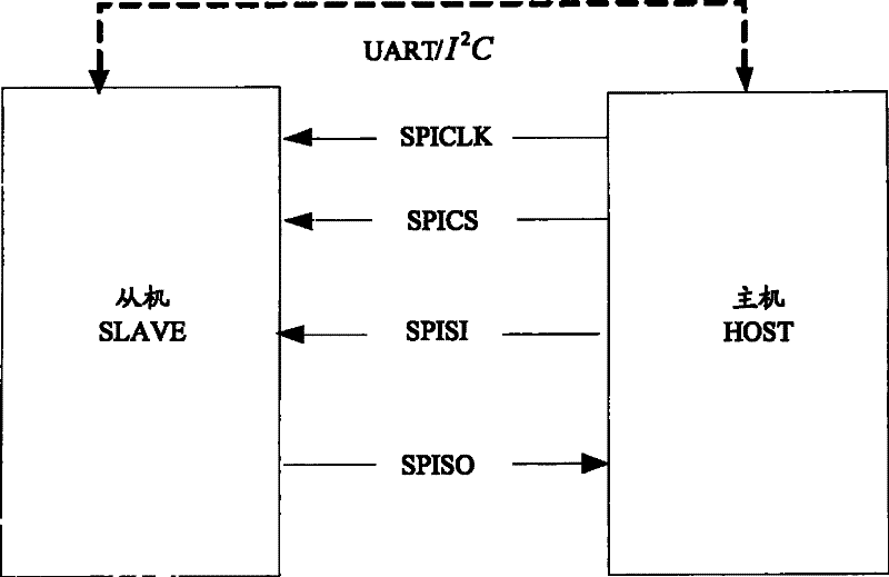
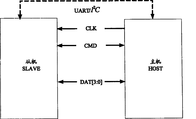
technical field [0001] The invention relates to the field of data transmission, in particular to a receiving device, an MMIS interface and a data interaction method. Background technique [0002] The serial peripheral interface SPI (Serial Peripheral Interface) bus system is a synchronous serial peripheral interface, which allows the master device to communicate and exchange data with various slave devices in a serial manner. The SPI system can be divided into single-wire mode and two-wire mode. The two-wire mode is mostly used and supports I 2 C bus or Universal Asynchronous Receiver Bus UART configuration port. see figure 1 As shown, based on the SPI two-wire mode, four lines are mainly used between the master device HOST (that is, SPI device) and the slave device SLAVE (such as: PDA, etc.): serial clock line (SPICLK), host input / slave output data Line SPISO, master output / slave input data line SPISI and active low slave select line SPICS. [0003] The secure digital i...

Claims


Application Information

Patent Timeline
Patent Type & Authority Patents(China)
IPC IPC(8): H04L29/10H04L29/12H04L12/40
Inventor 不公告发明人
Owner 新奇点智能科技集团有限公司
Learn More