Power transmission belt

A technology of belts and pulleys, applied in transmission belts, belts/chains/gears, V-belts, etc., can solve problems such as difficult rubber penetration

Active Publication Date: 2009-06-10
THE GATES CORP
View PDF9 Cites 10 Cited by
  • Summary
  • Abstract
  • Description
  • Claims
  • Application Information

AI Technical Summary

Problems solved by technology

Second, prior art nonwovens have very limited stretch or elongation
Third, it has previously been difficult to control the penetration of rubber into nonwovens to obtain the desired surface properties, especially when accompanied by tearing issues

Method used


Image

  • Power transmission belt
  • Power transmission belt
  • Power transmission belt

Examples


example

[0045] The following examples are provided to illustrate the essence of the invention and are not intended to limit its scope.

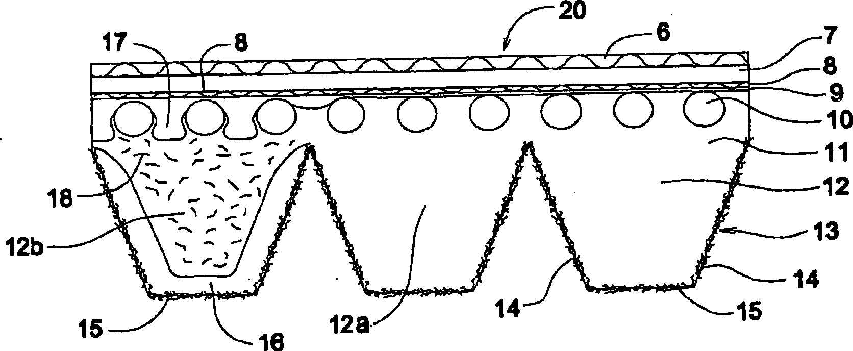
[0046] The first set of examples illustrates the process improvement of the belt of the present invention over the prior art. The belt tested included an upper cord 7, a crossover cord 8, a gum layer 9, a tensile cord 10, a compression portion or body 11, and a nonwoven area 15 on a profile with multiple v-ribs, such as figure 1 shown. The belts tested used an EPDM-based elastomeric material, polyester stretch cords, nylon cross cords, and two layers of nonwovens of various compositions, as shown in Tables 1 and 2. The nonwovens in Tables 1 and 2 were produced by a wet-laid process with PVAL bonds under comparable processing conditions. The stated ingredient percentages are based on fiber content only, ignoring binder content comprising from about 15% to about 22% by weight of the total nonwoven. For Examples 4, 6, and 8, the PVAL bond included me...


PUM

PropertyMeasurementUnit
diameteraaaaaaaaaa
diameteraaaaaaaaaa
lengthaaaaaaaaaa

Abstract

A power transmission belt (20) comprising a body (11) comprising an elastomeric material and having tensile members (10) running in a longitudinal direction, the body having a pulley-engaging region (12) having a profile; the pulley-engaging region comprising a fibrous nonwoven fabric material (15); characterized in that the fibers of the nonwoven material comprise acrylic fibers. The acrylic fibers are preferably micro-fibers of less than about 1.5 dpf and having an average diameter of 13.5 microns or less and an average length of about 1 to about 10 mm. The nonwoven material may be commingled with the elastomeric material in the pulley engaging region. Up to about 75% by weight of the fibers of the nonwoven material may comprise non-acrylic fibers such as other synthetic fibers, naturalfibers, or cellulosic fibers.

Description

technical field [0001] The present invention relates to a power transmission belt having an engineered surface, and more particularly to a power transmission belt having an engineered surface comprising a region having a nonwoven material comprising acrylic fibers. Background technique [0002] It is known in the art to manufacture power transmission belts from elastomeric materials with embedded stretchable members. Belts can be described as ribbed, toothed V-belts or flat profiles. The belt runs in pulleys with matching profiles. [0003] It is known to use various textile materials or fibers to cover the surface of the belt, including the back, sides, profile and / or wedge sides, to modify the abrasion resistance, friction properties, rupture resistance of the surface and / or the underlying elastomeric regions , stiffness and / or strength properties. Specific fabric properties and / or processes may be required to mold the profile. For example the fabric may be pre-formed ...

Claims


Application Information

Patent Timeline
Patent Type & Authority Applications(China)
IPC IPC(8): F16G5/20D04H1/43D04H1/4374
CPCF16G1/28F16G5/20F16G5/06F16G1/04F16G1/00
Inventor 吴翔L·C·哈尔
Owner THE GATES CORP
Why Eureka
Try Eureka