Sensor device with adaptive field compensation

A compensator, magnetic sensor technology, applied in instruments, scientific instruments, measurement of magnetic bead-labeled molecules, etc., can solve problems such as signal errors

Inactive Publication Date: 2009-06-10
KONINKLIJKE PHILIPS ELECTRONICS NV
View PDF5 Cites 15 Cited by
  • Summary
  • Abstract
  • Description
  • Claims
  • Application Information

AI Technical Summary

Problems solved by technology

The problem with this magnetic sensor device is that the GMR is affected by relatively strong ex

Method used


Image

  • Sensor device with adaptive field compensation
  • Sensor device with adaptive field compensation
  • Sensor device with adaptive field compensation

Examples


Embodiment Construction

[0041] Like reference numbers in the figures refer to the same or similar components.

[0042] Magnetoresistive biochips have good properties for biomolecular diagnostics in terms of sensitivity, specificity, integration, ease of use, and cost. Examples of such biochips are for example carried out in WO2003 / 054566, WO 2003 / 054523, WO 2005 / 010542A2, WO 2005 / 010543A1 or Rife et al. (Sens.Act.A vol.107, p.209 (2003)) description, all of which are incorporated into this application by reference.

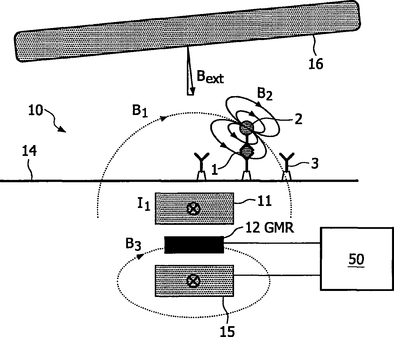
[0043] figure 1 The principle of a single sensor 10 for detecting superparamagnetic particles or magnetic beads 2 is illustrated. A magnetic (bio)sensor device consisting of an array (e.g., 100) of such sensors 10 can be used to simultaneously measure a large number of different biological target molecules 1 (e.g., proteins, DNA, amino acids, etc.) in solution (e.g., blood or saliva). )concentration. In one possible example of a binding scheme, the so-called "sandwich method", this i...


PUM


Abstract

The invention relates to a magnetic sensor device comprising an excitation wire for the generation of an alternating magnetic excitation field (Bi) and a GMR sensor (12) for sensing reaction fields (B2) generated by magnetized particles (2) in reaction to the excitation fields. Moreover, it comprises a compensator (15) for the generation of a magnetic compensation field (B3) that adaptively cancels predetermined spectral components of all magnetic fields (B2, B3) which lie in the sensitive direction of the magnetic sensor element (12). Measurements of the GMR sensor (12) are thus made robust against gain variations of the sensor.

Description

technical field [0001] The invention relates to a magnetic sensor device comprising at least one magnetic field generator and at least one associated magnetic sensor element. Also, the invention includes the use of such a magnetic sensor device as well as a method for detecting magnetic particles in a region of interest. Background technique [0002] A magnetic sensor device is known from WO 2005 / 010543 A1 and WO 2005 / 010542 A2, which can be used, for example, in microfluidic biosensors for detecting biomolecules labeled with magnetic beads. The microsensor device is provided with a sensor array comprising excitation wires for generating an excitation magnetic field and Giant Magneto Resistances (GMRs) for detecting the reaction field generated by magnetized magnetic beads. Also, the signal of GMR indicates the number of magnetic beads near the sensor. The problem with such magnetic sensor devices is that the GMR is affected by relatively strong excitation fields as well a...

Claims


Application Information

Patent Timeline
IPC IPC(8): G01R33/09G01N33/543
CPCG01R33/093G01R33/12G01R33/1269G01N27/745B82Y25/00G01N33/54326
Inventor H·杜里克J·A·H·M·卡尔曼
Owner KONINKLIJKE PHILIPS ELECTRONICS NV
Why Eureka
Try Eureka