Novel stirring station

A mixing station, a new type of technology, applied in mixing plants, cement mixing devices, control devices, etc., can solve the problems of restricting the quality of construction projects, high equipment investment, restricting the improvement of user construction capabilities and technical levels, etc.

Inactive Publication Date: 2009-06-17
陕西长大西筑路面机械科技有限公司
View PDF0 Cites 25 Cited by
  • Summary
  • Abstract
  • Description
  • Claims
  • Application Information

AI Technical Summary

Problems solved by technology

This high investment in equipment seriously restricts the improvement of the user's construction ability and technical level, and also seriously restricts the improvement of the quality of construction projects.

Method used


Image

  • Novel stirring station
  • Novel stirring station
  • Novel stirring station

Examples


no. 1 example

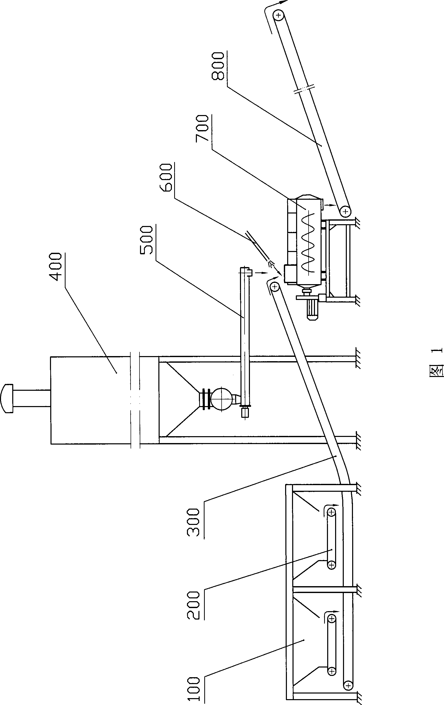
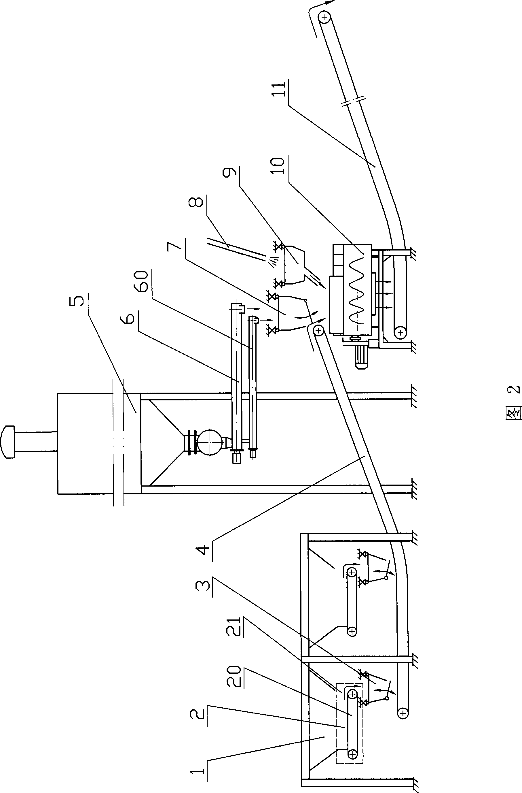
[0038] Referring to Fig. 2, the present invention includes an aggregate batching bin 1, a variable feeding system 2, an aggregate weighing hopper 3, an aggregate belt conveyor 4, a cement storage bin 5, a cement conveyor 6, a cement weighing hopper 7, and a water pump 8. Water weighing bucket 9, mixing tank 10 and discharge belt conveyor 11.

[0039]The bottom of the aggregate batching bin 1 is provided with a material outlet 21, the variable feeding system 2 is arranged below the outlet 21 of the aggregate batching bin 1, and the aggregate weighing hopper 3 is arranged under the variable feeding system 2. The material belt conveyor 4 is arranged below the aggregate weighing hopper 3, and the mixing tank 10 is arranged below the aggregate belt conveyor 4. A cement screw conveyor 6 is arranged below the cement storage bin 5 , and a cement weighing bucket 7 is arranged below the cement screw conveyor 6 . A water weighing bucket 9 is arranged below the water pump 8, and the mixi...

no. 2 example

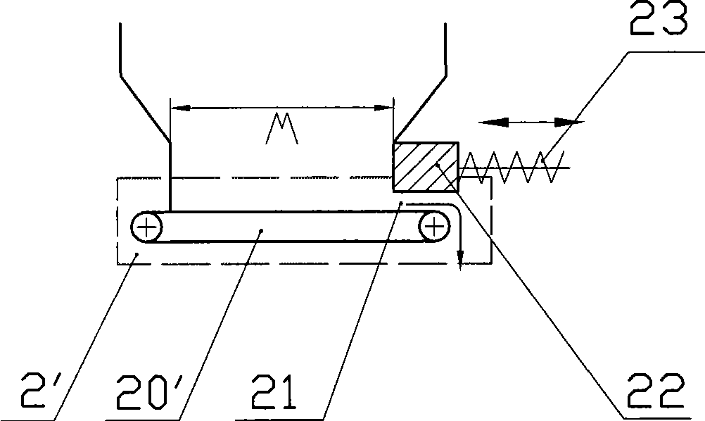
[0046] Such as image 3 As shown, the difference between the second embodiment and the first embodiment is that the feeding belt conveyor 20' in the second embodiment is a feeding belt conveyor rotating at a uniform speed, and a discharge port 21 of the aggregate batching bin 1 is provided with a The movable material door 22, the variable feeding system 2' includes the feeding belt conveyor 20' and the material door 22, the material door 22 is connected with the screw rod 23, the screw rod 23 is controlled by the motor, and the screw rod 23 controls the material door 22 in the horizontal direction, thereby changing the opening width W of the discharge port 21 in the horizontal direction. When working, the material gate 22 moves to the right along the horizontal until the width W of the discharge port 21 reaches the maximum. Moving to the left, the opening width W gradually becomes smaller, thereby controlling the batching discharge speed, and slowly sending the batching into t...

no. 3 example

[0048] Such as Figure 4 As shown, the difference between the third embodiment and the second embodiment is that the material door 22' in the third embodiment is arranged vertically and can move in the vertical direction, thereby changing the vertical direction of the discharge port 21 The opening height H above. When working, the material gate 22 moves vertically upwards along the discharge port 21 until the opening height H reaches the maximum. 22' moves vertically downwards, and the height H of the discharge port gradually decreases, so as to control the discharge speed of the ingredients, and slowly send the ingredients into the aggregate weighing hopper 3 .


PUM


Abstract

The invention relates to a novel stirring station, which comprises a skeletal material mixing cabin of which the bottom is provided with a material outlet, a material feeding system positioned below the skeletal material mixing cabin, a skeletal material weighting hopper positioned below the material feeding system, a material collecting belt conveyor positioned below the skeletal material weighting hopper, a stirring cylinder positioned below the material collecting belt conveyor, a cement storage bin, a cement spiral conveyor, a cement weighting hopper, a water pump and a water weighting hopper, wherein the stirring cylinder is simultaneously positioned below the cement weighting hopper and the water weighting hopper; the material feeding system is a variable material feeding system and comprises a variable feeding belt conveyor, a material outlet and a material door; and the structure of the stirring cylinder can be replaced according to different stirring materials.

Description

technical field [0001] The invention relates to a new type of mixing station, which is mainly used for mixing base stabilization materials and cement concrete in roads, bridges, railways, airports and other projects. Background technique [0002] As we all know, the foundations of highways, railways, urban roads, airports and other projects are generally paved with stable materials. This kind of stabilized material is to add stabilizers, such as cement and lime, to bulk materials such as stone, sand, industrial waste, soil, etc., and then send them into the mixing tank together with an appropriate amount of water, and form cement stabilized materials or lime stabilized materials after mixing. That is to say, stable soil in engineering. At present, the vast majority of stabilized soil mixing plants use continuous forced mixing tanks. As shown in Figure 1: it uses a forklift to load bulk materials such as stone, sand, industrial waste, and soil into several aggregate batchin...

Claims


Application Information

Patent Timeline
Patent Type & Authority Applications(China)
IPC IPC(8): B28C9/02B28C5/14B28C7/02B28C7/06
Inventor 南文辉苟红侠
Owner 陕西长大西筑路面机械科技有限公司
Why Eureka
Try Eureka