Fast generating method for computation hologram of 3D model

A technology for calculating holograms and models, which is applied in the field of obtaining optical images with holographic technology, and can solve the problems of increased investment in computing equipment, long time consumption, and huge amount of calculation.

Inactive Publication Date: 2009-06-17
JINAN UNIVERSITY
View PDF1 Cites 10 Cited by
  • Summary
  • Abstract
  • Description
  • Claims
  • Application Information

AI Technical Summary

Problems solved by technology

Its technical bottleneck lies in the huge amount of calculation, which takes a long time; at the same time, the huge amount

Method used


Image

  • Fast generating method for computation hologram of 3D model
  • Fast generating method for computation hologram of 3D model
  • Fast generating method for computation hologram of 3D model

Examples


Embodiment

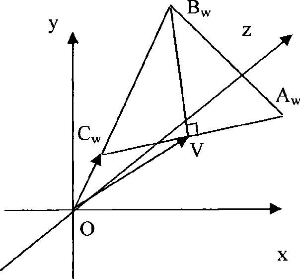
[0176] Such as Figure 8 As shown, the 3D model consists of four surfaces, namely △ABC, △ABD, △ACD, and △BCD. The coordinates of point A are (-0.85, 0, -0.68), the coordinates of point B are (0, 0, -0.34), the coordinates of point C are (-0.22, 0.36, 0.46), and the coordinates of point D are (- 0.63, 0.95, 0), the scale unit of the coordinate system is mm. The light field amplitude corresponding to each vertex: point A is 32, point B is 85, point C is 172, and point D is 40. Here, the unit of light field amplitude is volts / meter, and the following units are taken unless specified . The reference light selected here is a point light source, emitting spherical light waves, R 0 =0.001, the wavelength is 625nm, and the position coordinates are (0, 1, 300). The distance from the holographic surface to the origin in the world coordinate system is 500 mm, and the light field U of S(0.6, 0.3, 500) at a sampling point on the holographic surface s (0.6, 0.3, 500) initial value is 0...


PUM


Abstract

The invention discloses a computer generated hologram fast generation method for 3D models, comprising: translating and rotating a triangular patch in world coordinate system to standard position, and synchronously doing same transformation on the computer generated hologram, to hold the relative position between the triangular patches in the computer generated hologram and the object face, after the coordinate transformation of the triangular path; deriving Fresnel diffraction integral equation to obtain the relationship between the optical field at one point and the optical field at the top point of the triangular patch in the computer generated hologram; adding the coordinate and optical field of the top point of the special triangular patch into the equation to obtain the optical field at each sampling point on the computer generated hologram. The computer generated hologram fast generation method can significantly reduce calculation amount, avoid sampling error on object face and generate computer generated holograms of various resolutions.

Description

technical field [0001] The invention relates to a method for obtaining an optical image by using holographic technology, in particular to a method for rapidly generating a 3D model computational hologram. Background technique [0002] At present, the display of most 3D objects is realized by projecting onto a 2D plane, which loses the depth of field information, and the observer can only perceive 3D objects through clues such as occlusion relationships. The emergence of 3D stereoscopic display technology makes it possible to reproduce 3D scenes truly. [0003] By presenting two different parallax images to the left and right eyes, depth information of visual perception can be provided to achieve the purpose of three-dimensional display. Two-color anaglyph, anaglyph glasses, and polarizers are all stereoscopic display technologies that use the principle of "parallax image pair", but they all need to wear glasses, which is inconvenient to use; at the same time, there are some...

Claims


Application Information

Patent Timeline
IPC IPC(8): G06T15/00G06T15/50
CPCG03H1/0808G03H2210/45
Inventor 李军李艳辉武建华
Owner JINAN UNIVERSITY
Why Eureka
Try Eureka