Novel electronic horn for automobile and manufacturing method thereof

A technology for electronic horns and vehicles, which is applied in the direction of sound-generating devices and instruments, and can solve problems such as reduced horn life, ablation, and contact oxidation, and achieves the effects of reduced workshop management costs, simplified process, and reduced withstand voltage requirements

Active Publication Date: 2009-06-17
HARBIN GOODTIME ELECTRONICS
View PDF0 Cites 8 Cited by
  • Summary
  • Abstract
  • Description
  • Claims
  • Application Information

AI Technical Summary

Problems solved by technology

Due to a large current passing through the contacts, a high induced voltage is generated when the electromagnetic coil 6 contacts and disconnects, which breaks down the air and ablates the contacts, and the ablated contacts are easily oxidized, thus making the contacts The contact resistance increases, making the circuit unconnected, thus making the speaker invalid
Therefore, this kind of horn has very high requirements on the contacts. Many manufacturers even use platinum contacts, but they are still ablated by the high current of

Method used


Image

  • Novel electronic horn for automobile and manufacturing method thereof
  • Novel electronic horn for automobile and manufacturing method thereof
  • Novel electronic horn for automobile and manufacturing method thereof

Examples


Embodiment 1

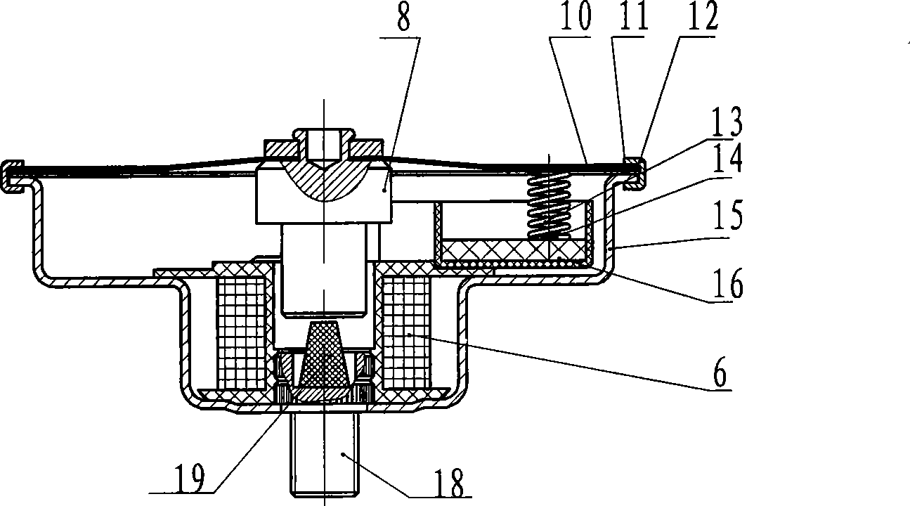
[0029] In this new type of automotive electronic horn, (see attached figure 2 ), which consists of: diaphragm 10, moving armature 8, static armature 18, conductive rubber 19, pressure ring 12, housing 15 and electronic switch circuit 16. The diaphragm 10 is connected with the movable armature 8, and the outer ring of the diaphragm 10 has a sealing insulating ring 11, and the diaphragm 10 is connected with the electronic switch circuit 16 through an electrical lead-out device. A counterbore is drilled at the center above the static armature 18, and a conductive rubber 19 is installed in the counterbore. The moving armature 8 and the static armature 18 are connected and disconnected through the conductive rubber 19 . The conductive rubber 19 is connected with the housing 15 through the static armature 18 . The diaphragm 10 and the sealing insulating ring 11 are riveted together with the casing 15 through the pressure ring 12 , but the diaphragm 10 and the casing 15 are insula...

Embodiment 2

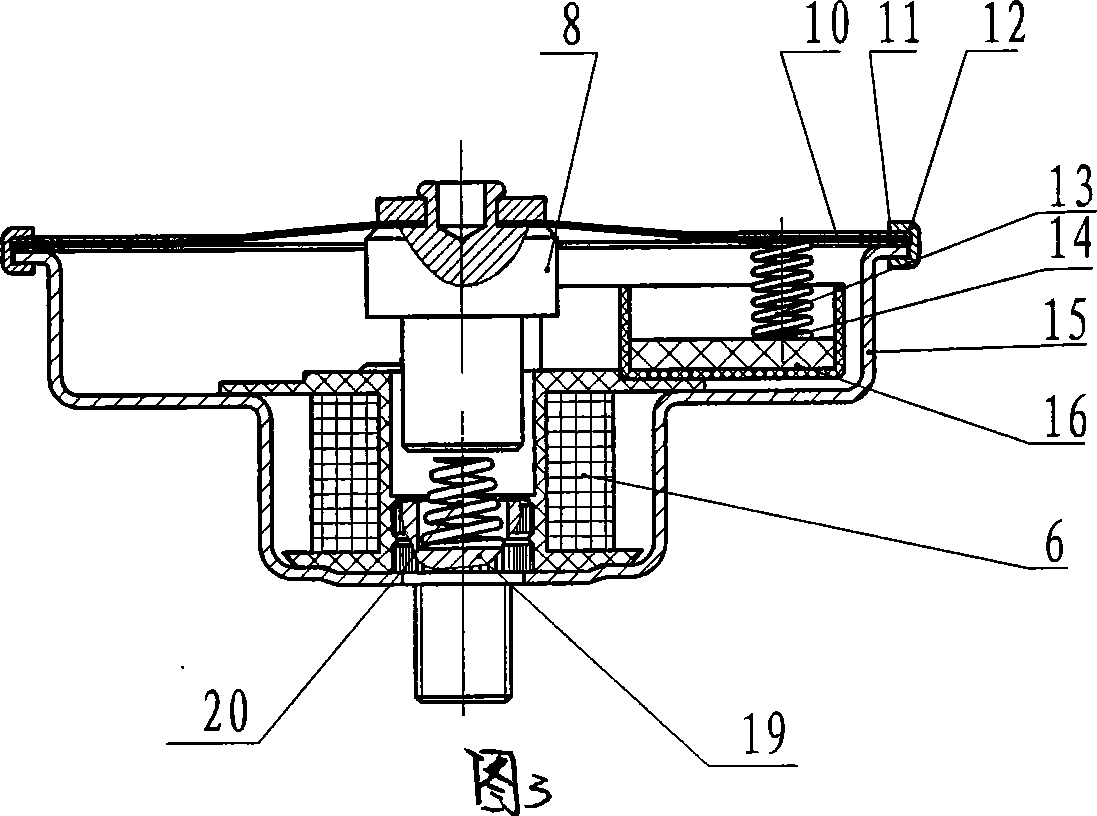
[0034] Similar to Embodiment 1 (see accompanying drawing 3), the difference is that the conductive rubber 19 in Embodiment 1 is changed into a tower spring 20.

[0035] In this novel vehicle electronic horn structure, a counterbore is drilled at the center above the static armature 19, and a tower spring 20 is installed in the counterbore. The static armature 19 is connected with the tower spring 20 by welding. The moving armature 8 and the static armature 19 are connected and disconnected through the tower spring 20 . The tower spring 20 is connected with the housing 15 through the static armature 19 .

[0036] In the electronic switch circuit 16, in the process of turning on and off the circuit, the tower spring 20 on the moving armature 8 and the static armature 19 reciprocally contacts and leaves, thereby driving the diaphragm 10 to vibrate and causing the horn to sound .

Embodiment 3

[0038] Similar to Example 1, (see attached Figure 4 ), the difference is that the conductive rubber 19 in the embodiment 1 is changed into a V-shaped shrapnel 22, and a counterbore is drilled at the center of the static armature 21 in the embodiment 1 and changed into a through groove for milling.

[0039] In this new type of vehicle electronic horn structure, a through groove is milled on the static armature 21 along the center line, and the V-shaped shrapnel 22 is welded in the middle of the groove, and the two ends of the V-shaped shrapnel 22 expose the static armature 21 of the upper surface. The static armature 21 is connected with the V-shaped shrapnel 22 by welding. The moving armature 8 and the static armature 21 are connected and disconnected through the V-shaped shrapnel 22 . The V-shaped shrapnel 22 is connected to the housing 15 through the static armature 21 .

[0040] In the electronic switch circuit 16, in the process of turning on and off the circuit, the m...


PUM


Abstract

The invention relates to a novel vehicle electronic horn and a manufacture method thereof, while prior mechanical horns have low stability and short service life. The vehicle electronic horn comprises a shell, a static armature connected with the shell, and a movable armature connected with a membrane, wherein the membrane is ringed by a seal insulation ring, the membrane provided with the seal insulation ring is connected with the shell via a press ring, the movable armature and the static armature are communicated or not via an elastic structure, and the membrane is connected with an electronic switch circuit via an electric lead-out device. The product can be used as vehicle horns.

Description

Technical field: [0001] The invention relates to a car horn and a manufacturing method thereof. Background technique: [0002] The mechanical horn structure of existing common metal contact (see attached figure 1 ) is to rivet the shrapnel 3, the insulating spacer 2, and the steel sheet 1 together, and then rivet two small upper tungsten contacts 4 and lower tungsten contacts 5 on the steel sheet 1 and the shrapnel 3 respectively. Through the contact and disconnection of the two contacts, the on-off of the circuit is realized, and the diaphragm 10 is driven to vibrate to make the horn sound. The mechanical horn of this metal contact has poor stability, low service life and complicated structure. In addition, the materials used for the contacts require high temperature resistance, corrosion resistance, and are expensive. The manufacturing method of making its loudspeaker is complicated, and the workshop management cost is high. There are many production beats, and the pro...

Claims


Application Information

Patent Timeline
IPC IPC(8): G10K9/13
Inventor 赵宏伟师学孟
Owner HARBIN GOODTIME ELECTRONICS
Why Eureka
Try Eureka