Converter circuit and method for operating such a converter circuit

A converter and circuit technology, which is applied to conversion equipment without intermediate conversion to AC, DC power input to DC power output, electrical components, etc., can solve problems such as energy transfer loss of capacitor energy storage, and achieve no loss. Effect

Inactive Publication Date: 2009-06-17
ABB (SCHWEIZ) AG
View PDF0 Cites 4 Cited by
  • Summary
  • Abstract
  • Description
  • Claims
  • Application Information

AI Technical Summary

Problems solved by technology

So in summary, the loss of energy transfer between capacitive accumulators is unacceptable for applications requiring high efficiency

Method used


Image

  • Converter circuit and method for operating such a converter circuit
  • Converter circuit and method for operating such a converter circuit
  • Converter circuit and method for operating such a converter circuit

Examples


Embodiment Construction

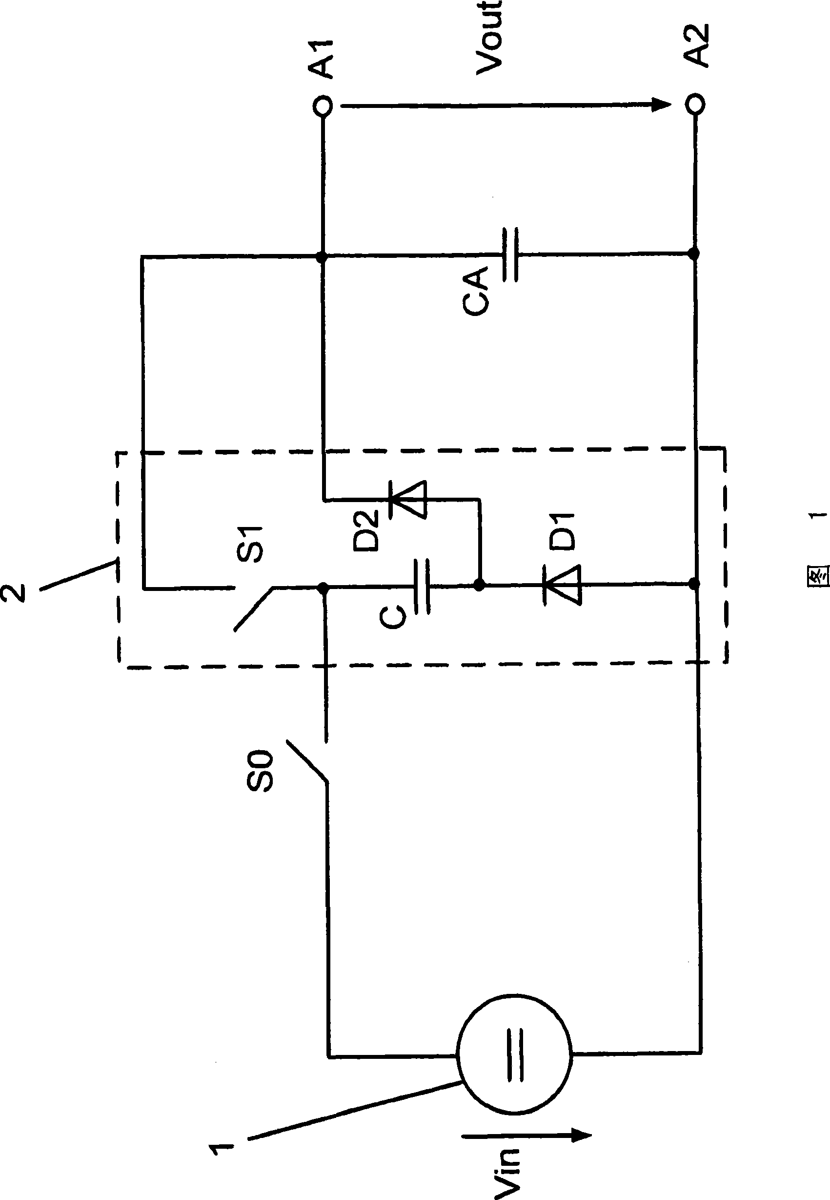
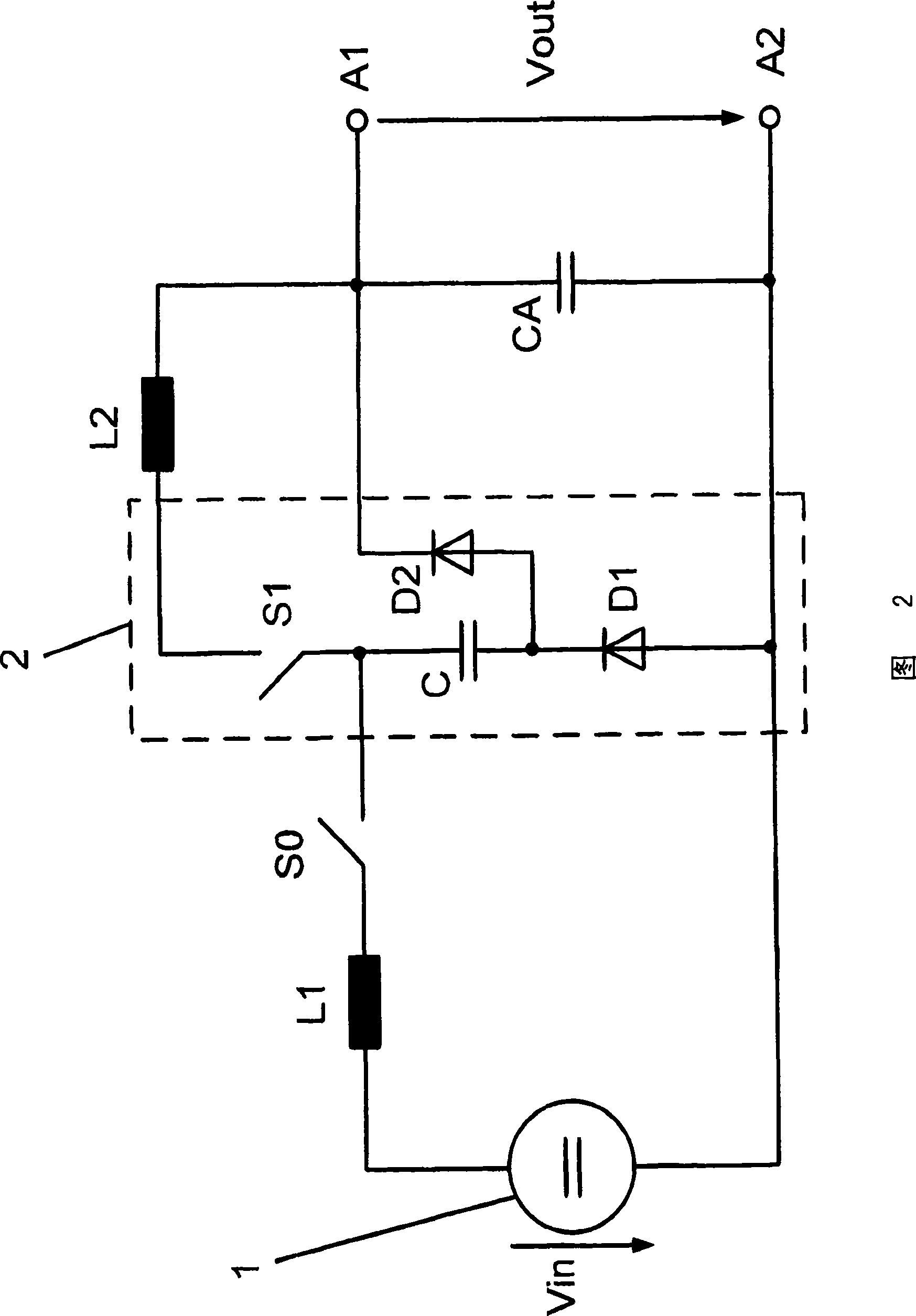
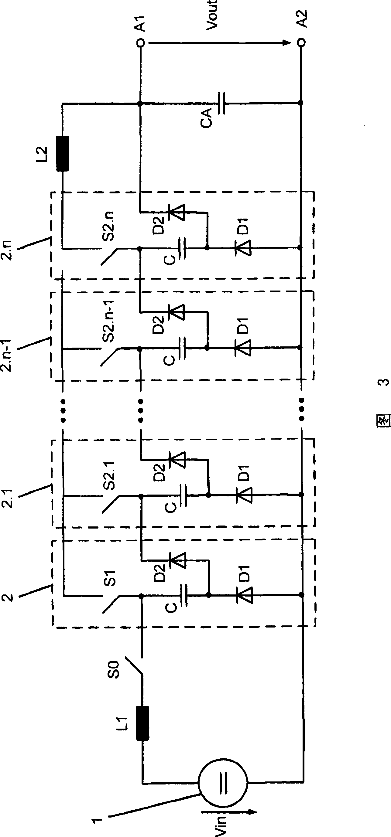
[0029] FIG. 2 shows a first embodiment of the converter circuit according to the invention. The converter circuit has a DC voltage source 1 and a first switch S0 connected to the DC voltage source 1 . Furthermore, the converter circuit also includes a switch group 2 with a second switch S1 , a first capacitive energy store C, first and second unidirectional non-controllable power semiconductor switches D1 , D2 . The first and second unidirectional non-controllable power semiconductor switches D1 , D2 are preferably designed as diodes. According to FIG. 2, the second switch S1 is connected to the first capacitive energy storage C, the first capacitive energy storage C is connected to the first unidirectional uncontrollable power semiconductor switch D1, and the second unidirectional uncontrollable power semiconductor switch D2 is connected to the first unidirectional uncontrollable power semiconductor switch D2. A capacitive energy storage C is connected to the connection poin...


PUM


Abstract

A converter circuit is specified in which, in order to avoid losses to the greatest possible extent, a first inductance is connected in series into the connection of a DC voltage source of the converter circuit to a first switch of the converter circuit, and in which, moreover, a second inductance is connected in series into the connection of a second switch of a switching group of the converter circuit to the junction point between a second capacitive energy store and a second unidirectional non-drivable power semiconductor switch of the switching group. Two further alternative converter circuits and also a method for operating the converter circuit are furthermore specified.

Description

technical field [0001] The invention relates to the field of power electronic circuits. The invention relates to a converter circuit and a method for its operation according to the preambles of the independent claims. Background technique [0002] Converter circuits are used today in power electronics applications. For example, it is conceivable to use the converter circuit as a DC voltage regulator, in particular as a step-down converter. For example, such a common conversion is shown in Fig. 1 according to "A new approach to reducing output ripple in switched-capacitor-based Steppdwon DC-DC-converters" (IEEE Transactions on Power Electronics, Vol 21, No.6, November 2006) circuit, especially DC voltage regulators. According to FIG. 1 , the converter circuit has a DC voltage source and a first switch connected to the DC voltage source. In addition, the converter circuit also includes a switch group having a second switch, a first capacitive energy store, a first and a se...

Claims


Application Information

Patent Timeline
Patent Type & Authority Applications(China)
IPC IPC(8): H02M3/10
CPCH02M3/07H02M2003/072H02M3/156Y02B70/10H02M3/072H02M1/0095H02M3/155H02M1/42
Inventor 徐庸硕P·斯泰默O·凯瑟
Owner ABB (SCHWEIZ) AG
Why Eureka
Try Eureka