

Annular flow duct for a turbomachine through which a main flow can flow in the axial direction
A flow channel, fluid machinery technology, applied in the components of pumping devices for elastic fluids, mechanical equipment, machines/engines, etc., can solve problems such as suboptimal flow direction of tributaries
- Summary
- Abstract
- Description
- Claims
- Application Information
AI Technical Summary
Problems solved by technology
Method used
Image

Examples
Embodiment Construction
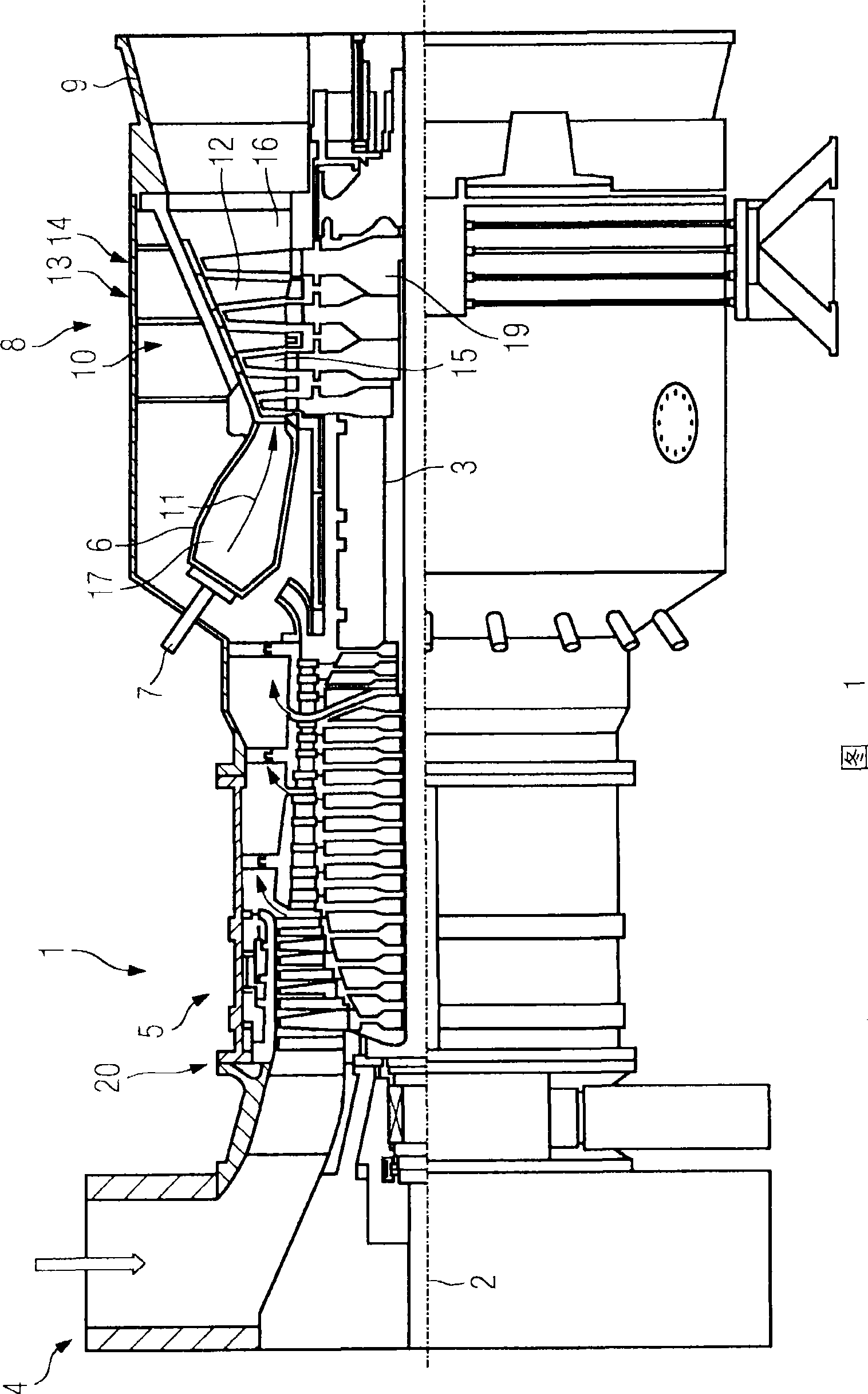
[0029] FIG. 1 shows a partial longitudinal section of a gas turbine 1 . Inside, it has a rotor 3 mounted in rotation about the machine axis 2 , which is also called a turbine rotor. Arranged successively along the rotor 3 is a suction housing 4 , a compressor 5 , a torus-shaped annular combustion chamber 6 with a plurality of burners 7 arranged rotationally symmetrically to one another, a turbine unit 8 and a smoke extraction chamber 9 . The annular combustion chamber 6 forms a combustion chamber 17 connected to an annular hot gas channel 16 . There, four successively connected turbine stages 10 form the turbine unit 8 . Each turbine stage 10 is formed, for example, from two blade rings. Viewed in the direction of flow of the hot gas 11 generated in the annular combustion chamber 6 , a rotor blade set 14 formed by rotor blades 15 correspondingly follows a guide vane set 13 in the hot gas channel 16 . The guide blades 12 are fastened to the stator, whereas the rotor blades 1...
PUM
 Abstract
Description
Claims
Application Information