Air shutter and installation method thereof
A technology for shutting off air and airflow, applied in the field of air shut-off, can solve problems such as increasing energy consumption, reduce pressure loss, and maintain the effect of blocking the intrusion of external impurities
- Summary
- Abstract
- Description
- Claims
- Application Information
AI Technical Summary
Problems solved by technology
Method used
Image
Examples
no. 1 example
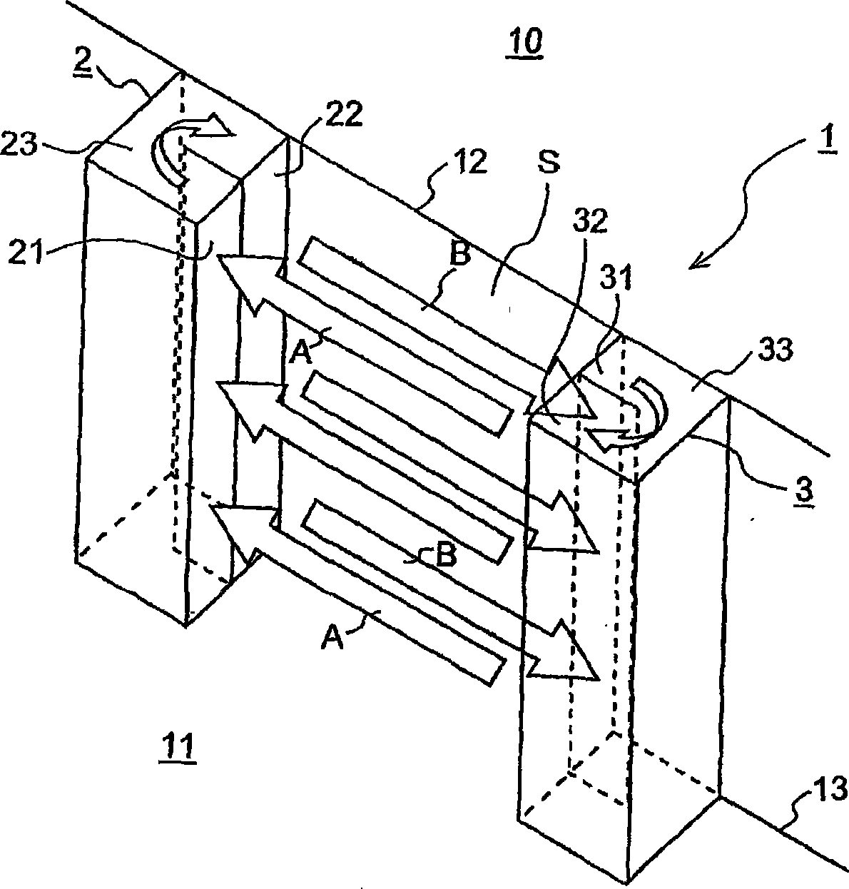
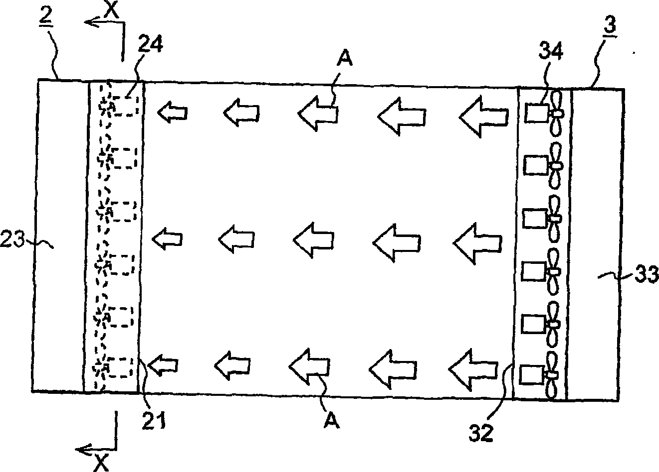
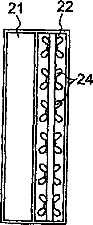
[0054] Refer below figure 1 To 3 to explain the first embodiment of the anti-insect / dust-proof air shutter.
[0055] The air shutoff device 1 is installed at the entrance of the storage space 10 . The passage space S is provided between the storage space 10 and the space 11 other than the storage space. The passage space S is formed by the ceiling part 12, the floor part 13, the left side wall part, and the right side wall part.
[0056] The shutter 1 has a left side casing 2 and a right side casing 3 that are located at opposite positions across a passage space S, respectively. The left case 2 is located on the left side wall portion side and the right side case 3 is located on the right side wall portion side.
[0057] The left case 2 is divided into two in the depth direction of the passage space S, and has a suction opening 21 and a discharge opening 22 , both openings facing the passage space S. As shown in FIG. The air passage 23 is formed by dividing the left side h...
no. 2 example
[0078] Refer below Figures 4 to 6 Now to explain the second embodiment of the insect-proof / dust-proof air shutter. A detailed explanation of the same structure as that of the first embodiment will be omitted.
[0079] The air shutoff device 1 is installed at the entrance of the storage space 10 . The shutter 1 has a left side casing 2 and a right side casing 3 at opposite positions across the passage space S, respectively.
[0080] In the second embodiment, the left case 2 is vertically divided into two parts, and has a suction opening 21 and a discharge opening 22 both facing the passage space S. As shown in FIG. The air passage 23 is formed by a part in the left side case 2 to allow the suction opening 21 to communicate with the discharge opening 22, so that the circulating air flow A vertically reverses its flow direction by 180° in the air flow reverse part of the air passage 23, and flows from the discharge The openings 22 are ejected as a recirculating air flow B.
...
no. 3 example
[0106] Figure 13 is a schematic perspective view of a third embodiment of the present invention. Fig. 14a is a longitudinal sectional view of the installed state of the insect / dust-proof air shut-off device of the third embodiment, which shows that in the cargo handling room between the storage room and the external space, the goods are moved from the truck into the storage space or from the storage space; The hanging door (vertical sliding door) is opened when the storage space is moved into the truck; Figure 14b is a section taken along line C-C in Figure 14a. Figure 15 is shown when the Figure 13 A graphical representation of the temperature over time in a storage room with and without an air curtain formed. Figure 16a is a graph showing the vertical distribution of air velocity through the doorway in the lateral central region of the doorway opening when there is a temperature difference between the exterior and interior; Figure 16b It is a diagram showing velocity ...
PUM
 Abstract
Description
Claims
Application Information
 - R&D
- Intellectual Property
- Life Sciences
- Materials
- Tech Scout
- Unparalleled Data Quality
- Higher Quality Content
- 60% Fewer Hallucinations
Browse by: Latest US Patents, China's latest patents, Technical Efficacy Thesaurus, Application Domain, Technology Topic, Popular Technical Reports.
© 2025 PatSnap. All rights reserved.Legal|Privacy policy|Modern Slavery Act Transparency Statement|Sitemap|About US| Contact US: help@patsnap.com


