Voltage-regulating converter for power of defibrillation and pacing apparatus

A buck-boost converter and flyback converter technology, which is applied in cardiac defibrillators, conversion equipment with intermediate conversion to AC, and adjustment of electrical variables, can solve the problem of increasing drive circuit steps, cost and complexity, and circuit Maximum duty cycle limitation, output voltage limitation, etc., to achieve the effect of convenient circuit stability design, direct and simple stability, and improved adjustment accuracy

Active Publication Date: 2009-06-24
SHENZHEN MINDRAY BIO MEDICAL ELECTRONICS CO LTD +1
View PDF0 Cites 26 Cited by
  • Summary
  • Abstract
  • Description
  • Claims
  • Application Information

AI Technical Summary

Problems solved by technology

[0005] 1) The main circuit cannot realize the isolation of input and output, and the input and output of the BUCK-BOOST circuit share the same ground, which cannot meet the requirement that the input and output of the pacing power supply must be isolated
[0006] 2) Although BUCK-BOOST can achieve a larger output voltage range, when the output voltage range is large, such as when the output changes from 10V to 150V, the circuit will be in the current discontinuous mode, the current critical mode and the current continuous mode. Therefore, the stability design of the converter loop becomes very difficult, and it cannot be guaranteed that the circuit is stable under the three operating modes
[0007] 3) The driving circuit is complex
There are two switching tubes Q1 and Q2 in the circuit. Q1 needs to be driven by high side, and Q2 is driven by low side. It is usually realized by gate drive transformer, which increases the steps, cost and complexity of the drive circuit. More importantly, , since the driving transformer needs a reset time, the maximum duty cycle of the circuit is limited, and the output voltage is limited

Method used


Image

  • Voltage-regulating converter for power of defibrillation and pacing apparatus
  • Voltage-regulating converter for power of defibrillation and pacing apparatus
  • Voltage-regulating converter for power of defibrillation and pacing apparatus

Examples


Embodiment Construction

[0026] Below according to accompanying drawing and embodiment the present invention will be described in further detail:

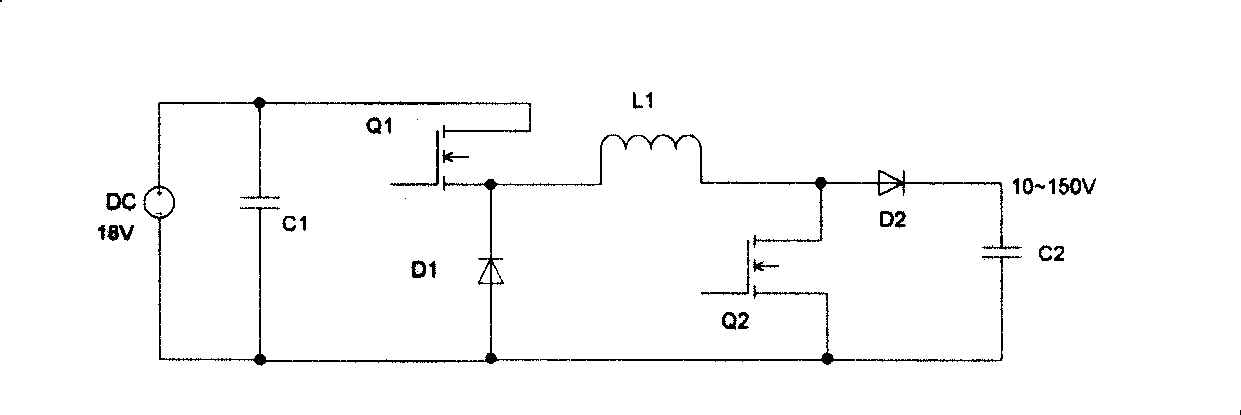
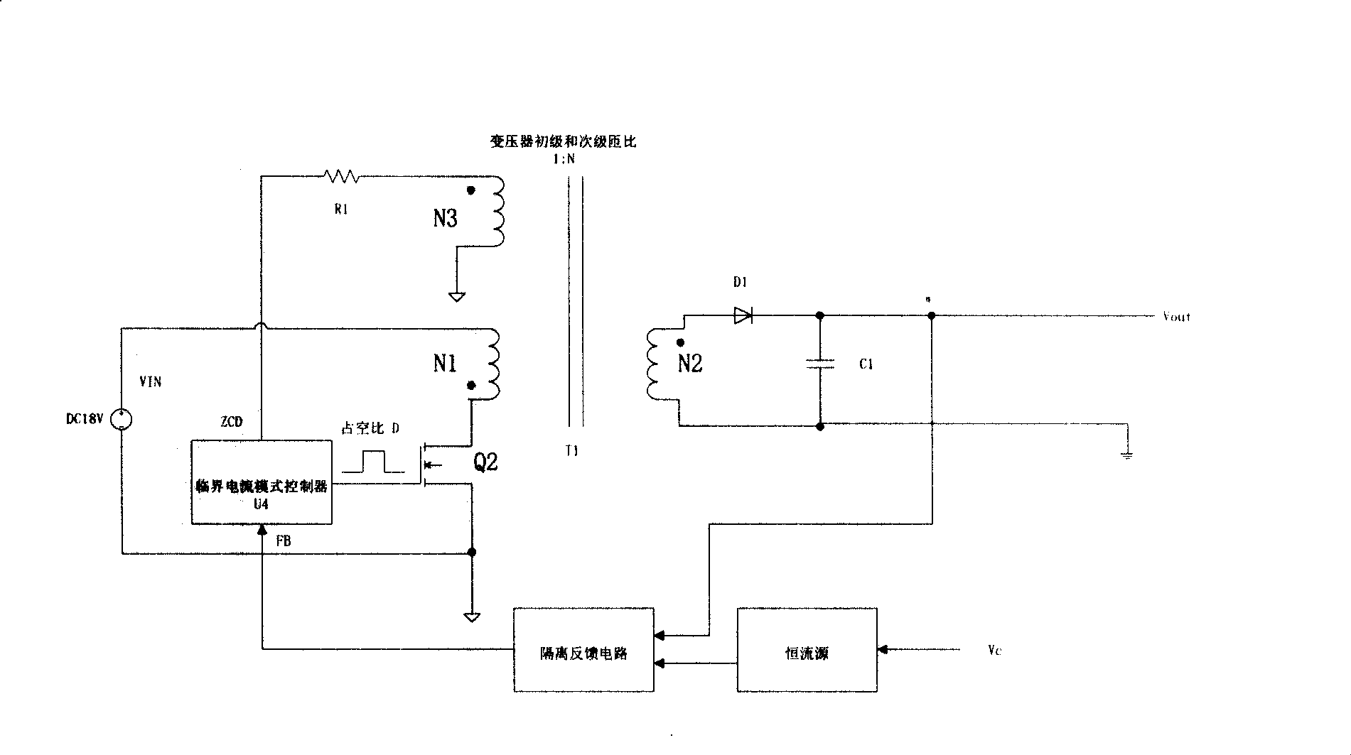
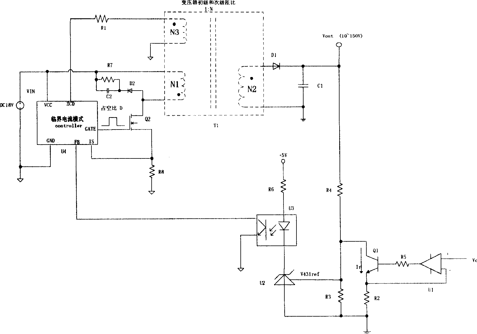
[0027] Such as figure 2 , 3 As shown, the buck-boost converter of the present invention includes four circuits, which are respectively a flyback converter (FLYBACK converter), a pulse width modulation controller (PWM controller), an isolated feedback circuit (Isolated Feedback) and an adjustable current source.

[0028] The FLYBACK converter includes a transformer T1, a switch tube Q2, a rectifier diode D1 and a capacitor C1. The primary winding N1 of the transformer is connected in series with the switch tube Q2 as the input terminal of the FLYBACK converter, and the secondary winding N2 of the transformer is connected in series with the rectifier diode D1 as the At the output end of the FLYBACK converter, the capacitor C1 is connected in parallel with the output end of the FLYBACK converter. The FLYBACK converter is used as the main circuit of the up...


PUM


Abstract

The invention relates to a buck-boost converter used in a defrillating and pacing power supply, which comprises a flyback converter, a PWM controller which is operated in a mode of critical current, an adjustable constant-current source and an isolated feedback circuit, wherein the flyback converter is used for realizing voltage change; the adjustable constant-current source is used for converting control voltage into a current control signal which is proportional with the control voltage; two input ends of the isolated feedback circuit are connected with a voltage output end of the flyback converter and the current control signal respectively; output voltage of the flyback converter is overlaid with the current control signal, and adjusting voltage is outputted and acts on a feedback voltage end of the PWM controller which is operated in the mode of critical current; and the PWM controller controls the switch-on time of a switch tube of the flyback converter according to the adjusting voltage and drives output voltage of the flyback converter to change. The buck-boost converter realizes isolation of input and output of the converter; the output voltage can be continuously changed within a large range lower than or higher than input voltage; and the control voltage VC and the output voltage form a linear proportional control relation.

Description

technical field [0001] The invention relates to a buck-boost converter for a power supply, in particular to a buck-boost converter used in a defibrillation and pacing power supply. Background technique [0002] The defibrillation monitor has a non-invasive pacing function, and can apply electrical stimulation through electrodes on the surface of the patient's chest to provide emergency treatment for bradycardia after defibrillation. For defibrillation and pacing, the voltage applied to the electrode needs to be controllable (that is, controlled by the control voltage) and continuously adjustable within a large range, that is, within its adjustment range, the output voltage may be higher or lower. at the input voltage. Since the electrodes directly act on the human body, the output voltage applied to the electrodes needs to be isolated from the input voltage to ensure safe use. [0003] At present, the implementation scheme of wide output voltage mainly adopts BUCK-BOOST co...

Claims


Application Information

Patent Timeline
Patent Type & Authority Applications(China)
IPC IPC(8): A61N1/378A61N1/39H02M3/28H02M3/335
Inventor 邵安岑张皖
Owner SHENZHEN MINDRAY BIO MEDICAL ELECTRONICS CO LTD
Why Eureka
Try Eureka