Tension measurement and control device of beam dyeing machine

A technology of a control device and a jigger, which is applied in the field of textile printing and dyeing, can solve the problems of inconstant cloth tension, large amount of dyeing cloth tape, light dyeing color, etc., and achieves the effect of simple structure

Inactive Publication Date: 2009-06-24
张同生
View PDF0 Cites 3 Cited by
  • Summary
  • Abstract
  • Description
  • Claims
  • Application Information

AI Technical Summary

Problems solved by technology

But its disadvantage is that there is head-to-tail color difference in the dyeing of the jigger, which is related to the unsteady tension of the cloth during dyeing. When the tension is high in the same dyeing, the amount of dyed cloth is less, the dyeing color is light, and the tension is small. The amount of dyed cloth is large, the color is deep, and the change of tension causes the color difference between the head and the tail of the same dyeing
At present, there is no reliable tension measurement and control device to measure the tension of the fabric when the jigger is dyeing

Method used


Image

  • Tension measurement and control device of beam dyeing machine
  • Tension measurement and control device of beam dyeing machine

Examples


Embodiment Construction

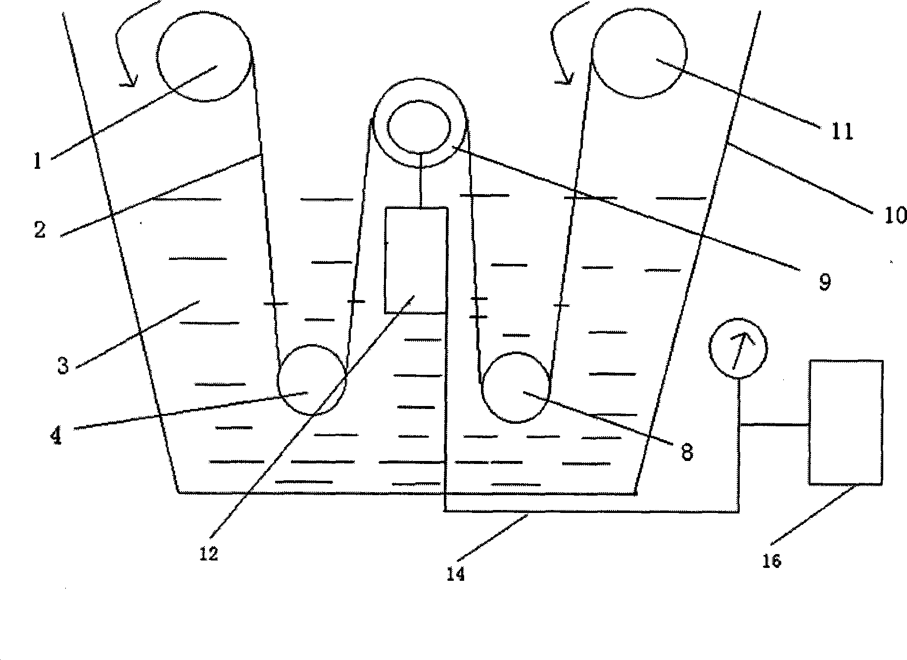
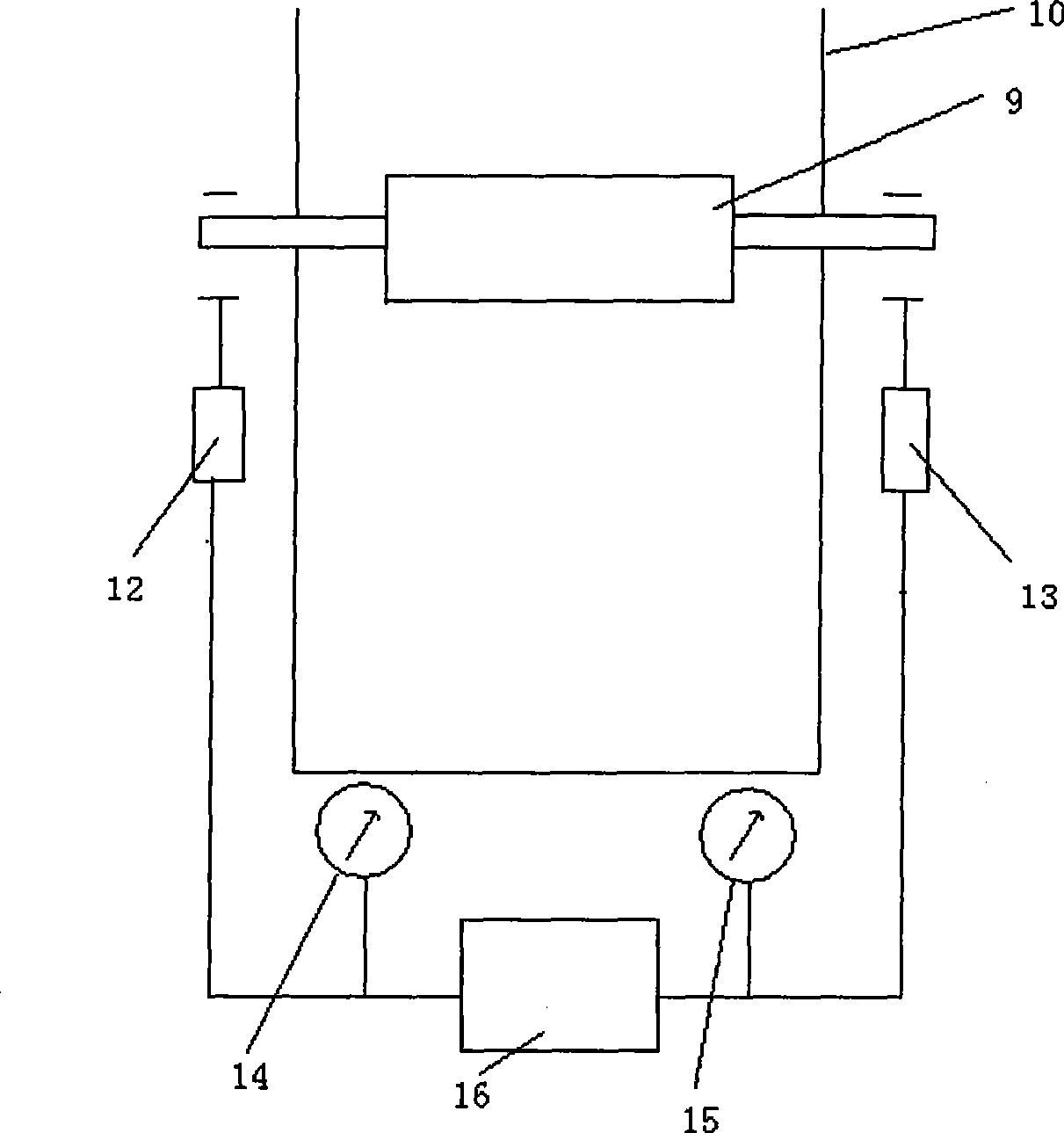
[0009] The present invention will be further described below in conjunction with accompanying drawing. figure 1 It is a measurement and control principle diagram of the tension measurement and control device of the dyeing jigger of the present invention; figure 2 It is a schematic diagram of the force measuring roller mechanism of the present invention.

[0010] A tension measurement and control device for a dyeing jigger provided by the present invention includes a casing 10 for containing the dye liquor 3, the first cloth winding roller 1 and the second cloth winding roller 11 are located above the dye liquor 3, and are respectively connected with a The variable frequency motor that can control its rotational speed and torque is connected. The first lower road roller 4 and the second lower road roller 8 are located inside the dye liquor 3. It is characterized in that: it also includes a The force-measuring roller 9 between the rollers 8, the force-measuring roller 9 is loc...


PUM


Abstract

The invention discloses a tension measuring and controlling device of a jig dyeing machine, which comprises a casing used for containing dye solution, a first cloth roller and a second cloth roller that is positioned above the first cloth roller; wherein, the first cloth roller and the second cloth roller are respectively connected with a variable-frequency motor that can control the rotating speed and the torque; the device also comprises a first lower track roller and a second lower track roller which are positioned inside the dye solution. The device is characterized by further comprising a force-measuring roller arranged between the first lower track roller and the second lower track roller; a first force-measuring bracket and a second force-measuring bracket are respectively arranged at the two sides of the force-measuring roller and outside the casing, and the two ends of a roll shaft of the force-measuring roller respectively act on the first force-measuring bracket and the second force-measuring bracket; the singles of a first electronic voltage-sensitive sensor used for measuring the pressure of the first force-measuring bracket and a second electronic voltage-sensitive sensor used for measuring the pressure of the second force-measuring bracket are transmitted into a control computer which can control the running of the variable-frequency motor that is respectively connected with the first cloth roller and the second cloth roller. The tension measuring and controlling device can realize the aim of immediately measuring and controlling the tension of cloth when the jig dyeing machine dyes.

Description

technical field [0001] The invention relates to a tension measurement and control device for a jigger, which belongs to the field of textile printing and dyeing. Background technique [0002] The textile printing and dyeing industry is an industry with high energy consumption and high pollution. Therefore, the development of dyeing machines with low energy consumption and low emissions is the goal of the printing and dyeing machinery manufacturing industry. Generally, the dye bath ratio of the overflow jet dyeing machine is about 1:20, that is, 1 kg of cloth (fabric) needs to be dyed with 20 kg of dye solution (most of which is water, and water accounts for about 99.98% of the dye solution). The dyeing bath ratio of the dyeing jigger is only about 1:3, and the lowest can be below 1:2. Compared with the overflow jet dyeing machine, it can save a lot of energy, mainly coal, electricity, water consumption, and dyeing sewage at the same time The emission is only about one tenth...

Claims


Application Information

Patent Timeline
Patent Type & Authority Applications(China)
IPC IPC(8): D06B3/32D06B23/00G01L5/04G05D15/01
CPCY02P70/62
Inventor 张同生
Owner 张同生
Why Eureka
Try Eureka