Cover locking device

A technology for locking devices and locking components, which is applied to washing devices, building locks, locks operated by non-mechanical transmission, etc., can solve the problems of overcurrent flowing through the motor, abnormal heating, and failure to miniaturize the motor, so as to prevent resonance and reduce The effect of small drive loads

Active Publication Date: 2009-06-24
NIDEC SANKYO CORP
View PDF2 Cites 11 Cited by
  • Summary
  • Abstract
  • Description
  • Claims
  • Application Information

AI Technical Summary

Problems solved by technology

Therefore, there is a problem that the motor for driving the locking member cannot be sufficiently miniaturized.
In addition, when the locking member is operated while the front end side of the locking member is blocked by sundries, etc., since the locking member cannot move forward, the motor may be locked and an overcurrent may flow through the motor, which may cause abnormal heating, etc. s reason

Method used


Image

  • Cover locking device
  • Cover locking device
  • Cover locking device

Examples


Embodiment Construction

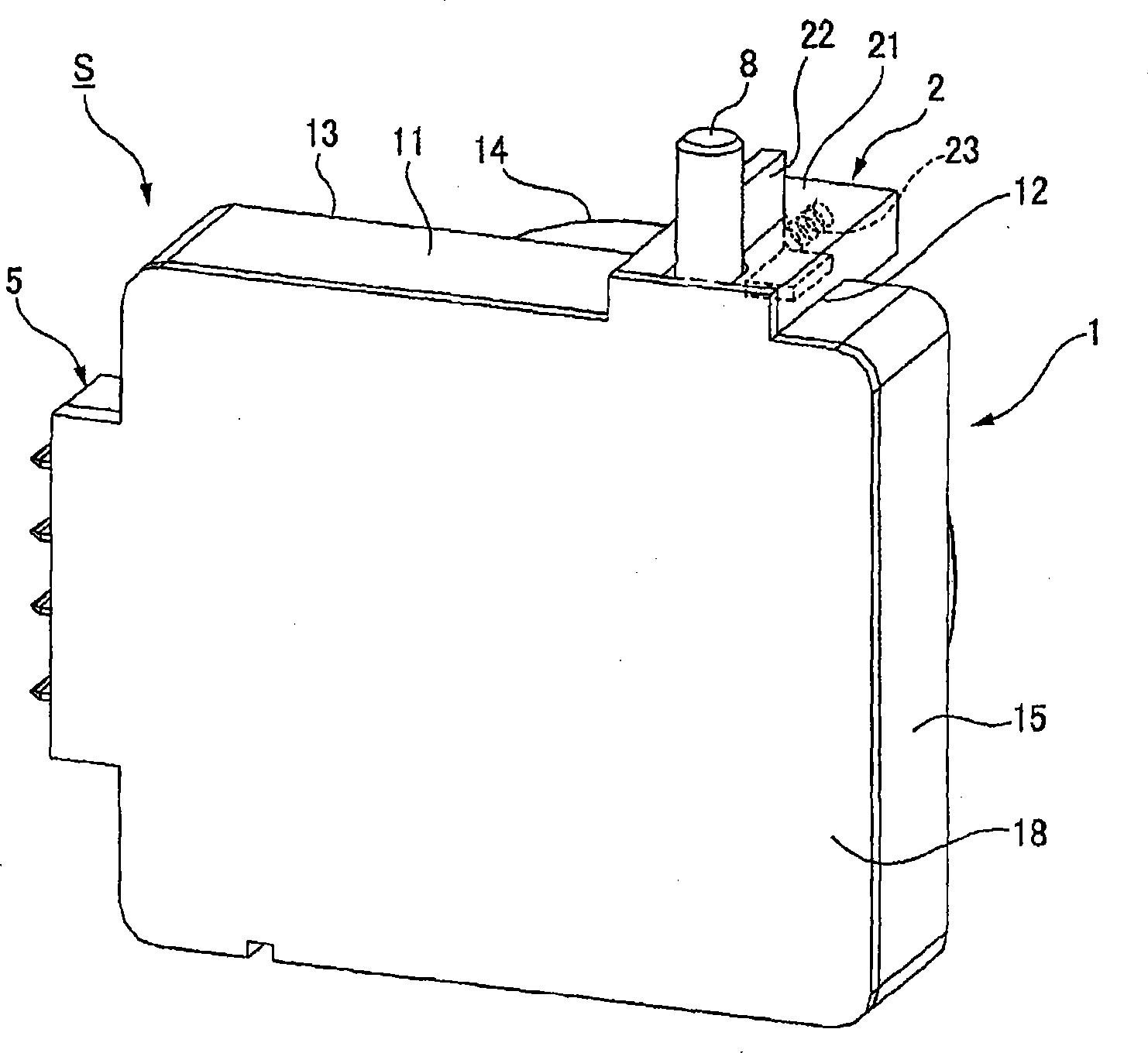
[0057] Next, an embodiment of the lid lock device to which the present invention is applied will be described with reference to the drawings.

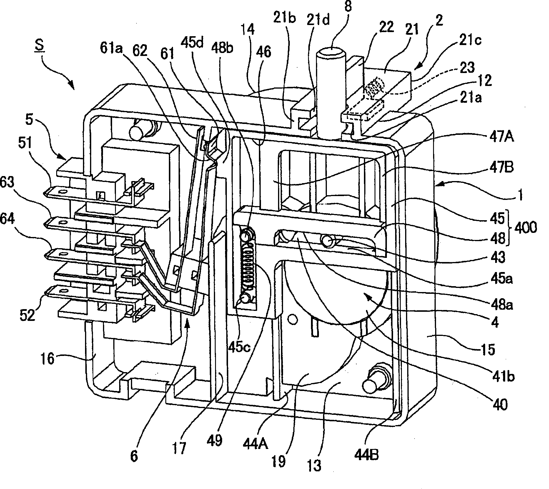
[0058] figure 1 is a perspective view of the lid locking mechanism, figure 2 It is a perspective view of the cover locking device omitting the end plate of the case,

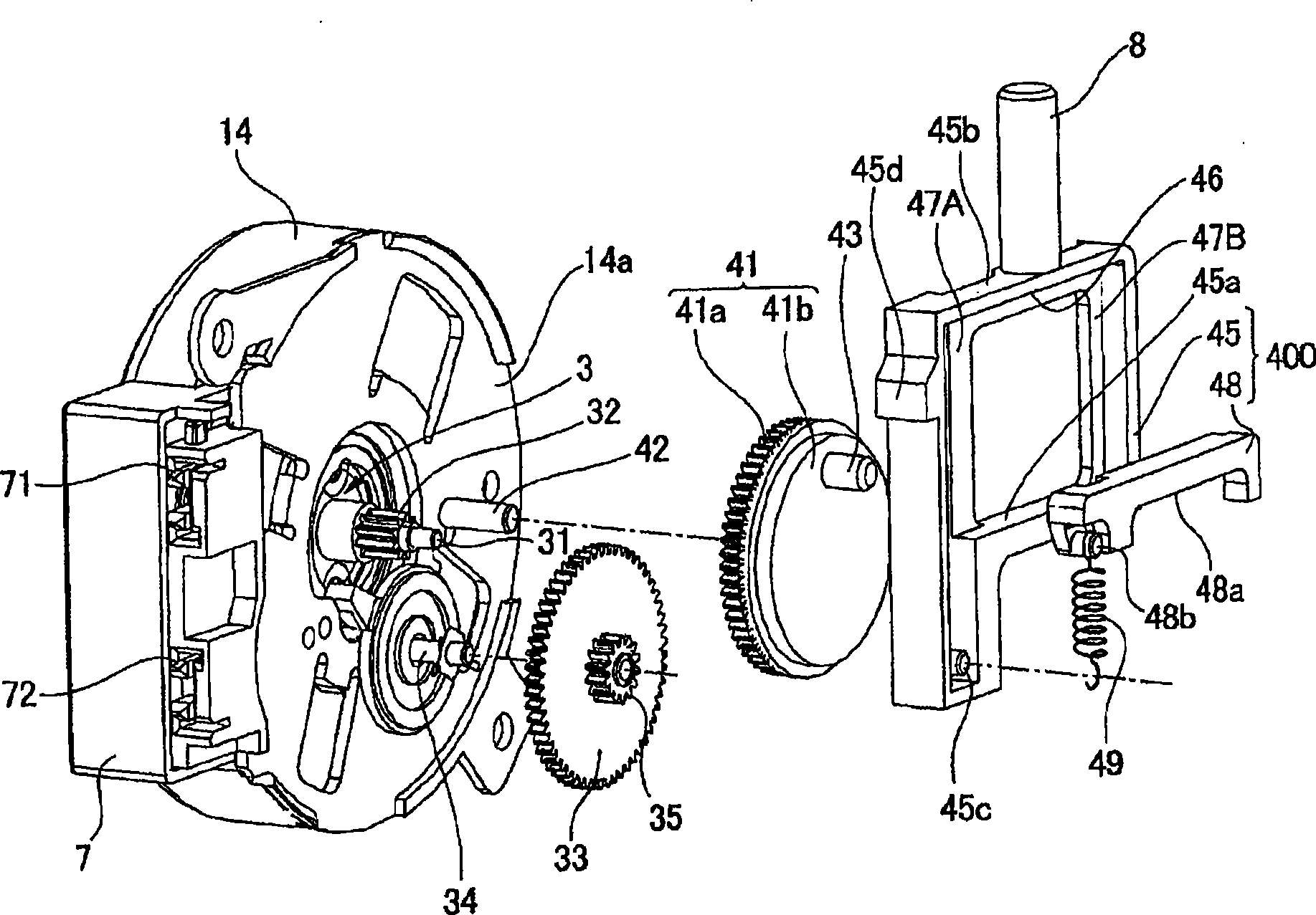
[0059] image 3 It is an exploded perspective view of the drive unit including the motor, Figure 4 It is an explanatory diagram of the operation of the cover locking device,

[0060] Figure 5 It is an explanatory diagram of a device with a cover lock installed.

[0061] (Structure of cover lock mechanism)

[0062] like figure 1 , figure 2 As shown, the lid locking device S includes a thin, substantially cuboid housing 1 . An opening 12 serving as a passage for a lock pin 8 , which is a lock member, is formed on a side surface (long side surface) 11 of the case 1 . The shutter mechanism 2 for opening or closing the passage of the lock pin 8 is provided in th...


PUM


Abstract

The present invention provides a cover locking device capable of manually relieving locking, which may be driven by small-sized electric motor and may restrain load to the motor and each components. The cover locking device (S) makes a first slide member (45) and a locking pin (8) move rectilinearly based on rotation of a camshaft gear wheel (41), such that the pin (8) move in and fro inside / outside a shell (1) from a gate mechanism (2) on side of the shell (1). A second slide member (48) may be assembled on the first slide member (45) in manner of sliding on in and fro direction of the pin (8). The first slide member (45) and the second slide member (48) are provided with cam surfaces (45a, 48a) opposite on slide direction, and form a cam groove (40) blocking with an eccentric pin (43) with the cam surfaces. The first slide member (45) and the second slide member (48) are connected by a screw spring (49), which applies force to effect in direction that the cam surface (45a, 48a) approaches each other.

Description

technical field [0001] The invention relates to a lid locking device for locking a lid body in a closed state. Background technique [0002] Conventionally, in an apparatus having an openable cover such as a washing machine or a dryer, the cover is locked in a closed state in order to prevent the cover from opening during operation. As a locking device for locking the cover, a locking member such as a locking pin is moved forward and backward by a driving source such as a motor to engage with an engaging hole (for example, refer to Patent Documents 1 and 2). [0003] In the lock pin driving structure described in Patent Document 1, a disc-shaped crank plate is attached to the output shaft of the motor and rotated, and the crank pin vertically arranged at an eccentric position deviated from the rotation center of the crank plate and The rectangular opening of the support member supporting the base end of the lock pin is engaged to move the lock pin forward and backward. The...

Claims


Application Information

Patent Timeline
IPC IPC(8): D06F39/14D06F58/20
CPCD06F37/28D06F37/42D06F39/14D06F2105/44E05B47/0012
Inventor 有贺久刚赤羽德行
Owner NIDEC SANKYO CORP
Why Eureka
Try Eureka