Laser radar scanning device

A scanning device and laser radar technology, applied in the field of laser radar scanning technology, can solve the problems of low scanning frequency and limited scanning range, and achieve the effects of good scanning effect, small driving load and stable performance

Pending Publication Date: 2019-07-09
BEIJING WATCH DATA SYST
View PDF22 Cites 3 Cited by
  • Summary
  • Abstract
  • Description
  • Claims
  • Application Information

AI Technical Summary

Problems solved by technology

[0004] In view of the above problems, the object of the present invention is to overcome the defects of low scanning frequency and limited scanning range in the prior art, and provide a laser radar scanning device

Method used


Image

  • Laser radar scanning device
  • Laser radar scanning device
  • Laser radar scanning device

Examples


Embodiment approach

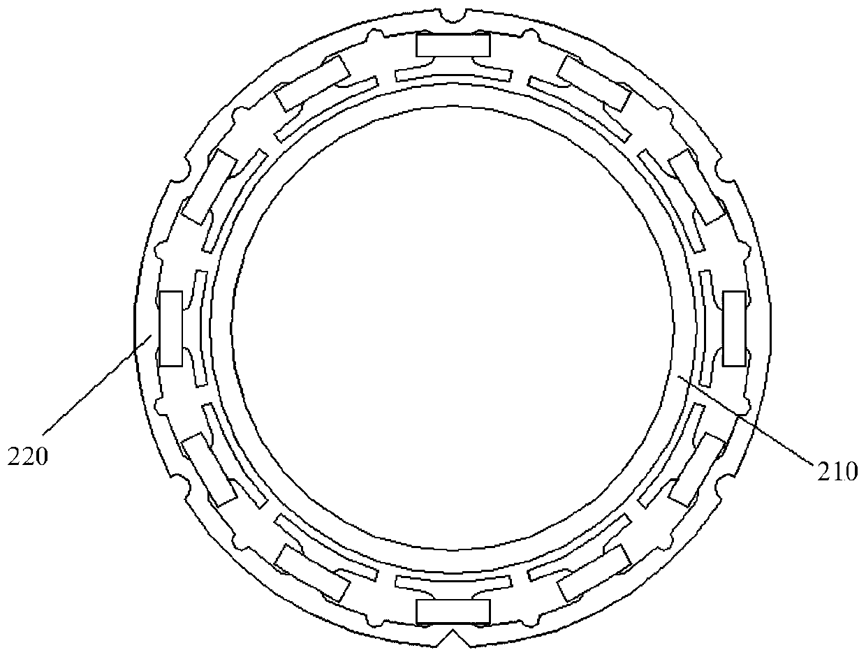
[0041] According to an embodiment of the present invention, the rotor 210 is a brushless motor rotor magnetic ring; the stator 220 is a brushless motor stator winding; the brushless motor rotor magnetic ring is located inside the brushless motor stator winding . The built-in rotor magnetic ring of the brushless motor and the external stator winding of the brushless motor form a brushless inner-rotating motor to drive the rotating frame 120 to rotate. The brushless motor relies on changing the alternating frequency and waveform of the current wave input to the stator winding of the brushless motor, and forms a magnetic field that rotates around the geometric axis of the motor around the winding coil, and this magnetic field drives the rotor magnet of the brushless motor. A permanent magnet on the ring turns to make the motor turn.

[0042] Figure 4 A schematic diagram of an embodiment of a rotating component according to the invention is shown.

[0043] Such as Figure 4 A...


PUM


Abstract

The invention discloses a laser radar scanning device. The device comprises a reflector, a rotary framework, a fixed framework and a laser receiving and transmitting component, wherein the rotary framework is of a hollow cylinder structure and has an axis center, and the rotary framework rotates around the axis center; the reflector is obliquely installed above the rotary framework to rotate alongwith the rotary framework; and the laser receiving and transmitting component is located below the reflector, fixed through the fixed framework and arranged to transmit and receive lasers, so that the transmitted lasers are reflected by the reflector to scan a surrounding detected object, and the lasers reflected by the surrounding detected object are received. According to the technical scheme,the device has the advantages that the structure is simple, performance is stable, manufacturing cost is low, automatic manufacturing is easy to implement, the scanning range is wide, and scanning frequency is controllable and adjustable.

Description

technical field [0001] The present invention generally relates to the fields of robots, AGV, laser scanning and the like, and more specifically relates to a laser radar scanning technology. Background technique [0002] In the prior art of laser scanning distance measuring devices, one type is the laser scanning radar whose laser transceiver is off-axis cn1052. This kind of radar laser transceiver module, grating decoder, main control board, etc. are installed on the motor rotor as rotating components, and the Rotating together, the power supply of the transceiver module and the main control board needs to adopt the method of coil electromagnetic induction wireless power supply, which has a complex structure, high cost, and low efficiency; while data transmission needs to use optical communication, which has a complex structure and poor stability; at the same time The laser transceiver is installed on the rotor structure of the motor and rotates together with the motor, resu...

Claims


Application Information

Patent Timeline
Patent Type & Authority Applications(China)
IPC IPC(8): G01S7/481
CPCG01S7/4817G01S7/4811
Inventor 吴限刘学文
Owner BEIJING WATCH DATA SYST
Why Eureka
Try Eureka