Unlock instant, AI-driven research and patent intelligence for your innovation.

Magnetically stabilized plasma flow ignition generator

A plasma jet and generator technology, which is applied to machines/engines, jet propulsion devices, gas turbine devices, etc., to solve the problems of stability and plasma jet generation, and improve the service life

Inactive Publication Date: 2009-06-24
HARBIN ENG UNIV
View PDF0 Cites 22 Cited by
  • Summary
  • Abstract
  • Description
  • Claims
  • Application Information

AI Technical Summary

Problems solved by technology

[0005] The purpose of the present invention is to provide a magnetically stable plasma flow ignition generator that can solve the problems of plasma arc stability and plasma jet generation under low current working conditions, and can greatly improve the service life of the generator

Method used


Image

  • Magnetically stabilized plasma flow ignition generator

Examples


Embodiment Construction

[0017] The present invention is described in more detail below in conjunction with accompanying drawing example:

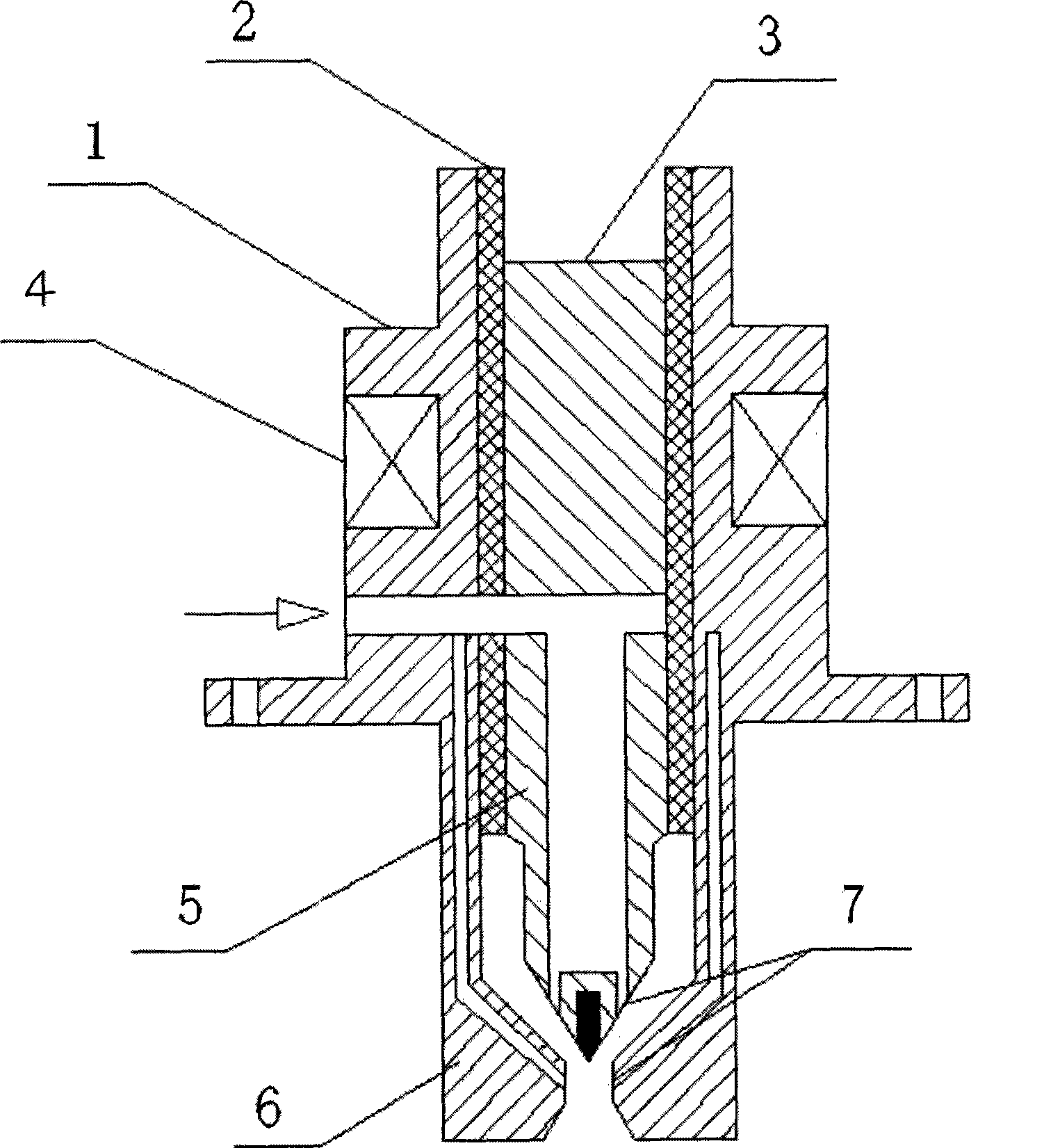
[0018] With reference to the accompanying drawings, the structure of the magnetically stable plasma flow ignition generator of the present invention includes a mount 1 , an insulator 2 , an inner pole 3 , a magnetically stable coil 4 , a cathode 5 , an anode 6 and a cyclone 7 .

[0019] The joint on the mounting base 1 is provided with a threaded interface to be connected with the high-voltage ignition cable, the inner pole 3 and the cathode 5 are closely connected, and the mounting base 1 and the anode 6 are of an integral structure and communicate with the earth.

[0020] The insulator 2 is made of high-temperature-resistant insulating material, which reliably insulates and separates the mounting base 1 from the cathode 5 to avoid short-circuit ignition. In this embodiment, the insulator 2 is made of insulating ceramic material.

[0021] The cyclone 7 and the c...


PUM


Abstract

The invention provides a magnetically stable plasma flow ignition generator. The ignition generator comprises a fitting seat, an insulator, a whirlcone, a cathode and an anode and is characterized in that a magnet-stabilizing coil is arranged outside the fitting seat; the fitting seat and the anode are combined into a whole with the inside thereof being a cavity, and an air inlet is arranged on the the side; the cathode is arranged in the cavity of the fitting seat and the anode, and the insulator is arranged between the cathode and the anode; the back part of the cathode is of sharp-pointed shape, and the sharp-pointed shape part is provided with a rotational flow exit-hole to form the whirlcone; the outlet of the anode is of a scaling nozzle shape, an inner compression horn matches with the cathode to compress and push the voltaic arc into the middle part of the anode and the ejected plasma jet flow is amplified by an enlargement horn to form a conical surface; an gas cooling vent is arranged on the anode, and an air inlet of the vent is arranged at an air inlet; the fitting seat is connected with a high voltage firing cable and grounded; an inner pole is arranged in the fitting seat, and the inner pole and the cathode are closely connected. In the invention, stability of the plasma arc and the occurrence of plasma jet flow under low current functional mode can be realized.

Description

(1) Technical field [0001] The invention relates to an igniter for an engine, in particular to an ignition generator suitable for a gas turbine. (2) Background technology [0002] Nowadays, gas turbines have been widely used and developed in many fields such as aviation, ships, and power generation due to their advantages such as high power, small weight and size, and high efficiency. During the start-up process of a gas turbine, ignition is critical. The success rate of ignition will be directly related to the safe and reliable operation of the whole device. [0003] At present, the commonly used gas turbine ignition methods include electric spark ignition and semiconductor surface discharge ignition. The ignition energy of the electric spark point is low and the ignition delay is long. Although the semiconductor surface discharge ignition can obtain a large ignition power, due to the life of the semiconductor, it directly affects the performance and life of the entire ig...

Claims


Application Information

Patent Timeline
IPC IPC(8): F02C7/266
Inventor 杨家龙郑洪涛谭智勇陈明敏
Owner HARBIN ENG UNIV
Features
  • R&D
  • Intellectual Property
  • Life Sciences
  • Materials
  • Tech Scout
  • Unparalleled Data Quality
  • Higher Quality Content
  • 60% Fewer Hallucinations
Learn More