
Fluid delivery device

A fluid conveying and fluid technology, applied in the field of fluid conveying devices, can solve the problems of consumption, high cost, and a large amount of fluid backflow.

Active Publication Date: 2010-12-08
MICROJET TECH
View PDF7 Cites 0 Cited by
  • Summary
  • Abstract
  • Description
  • Claims
  • Application Information

AI Technical Summary

Problems solved by technology

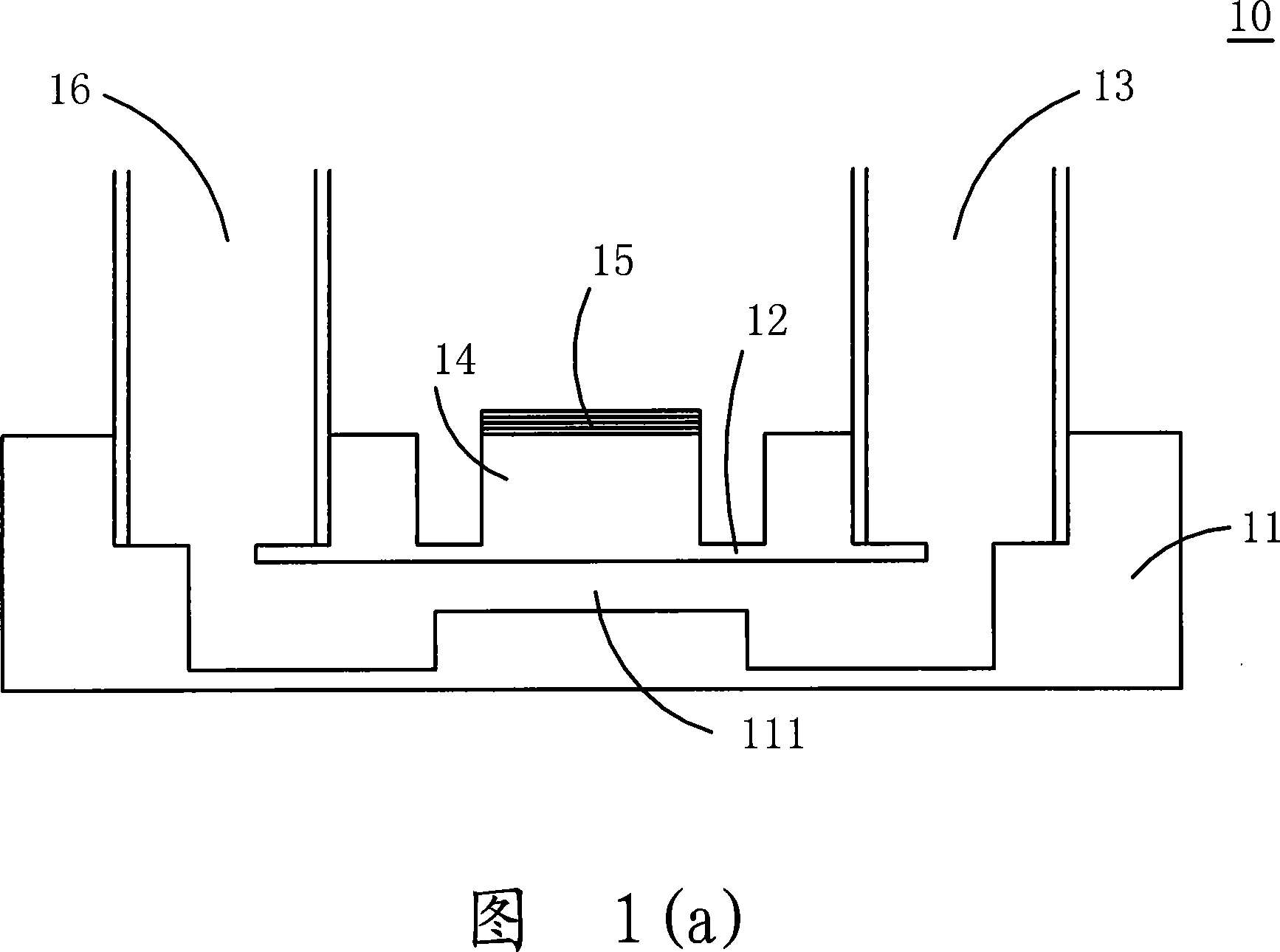
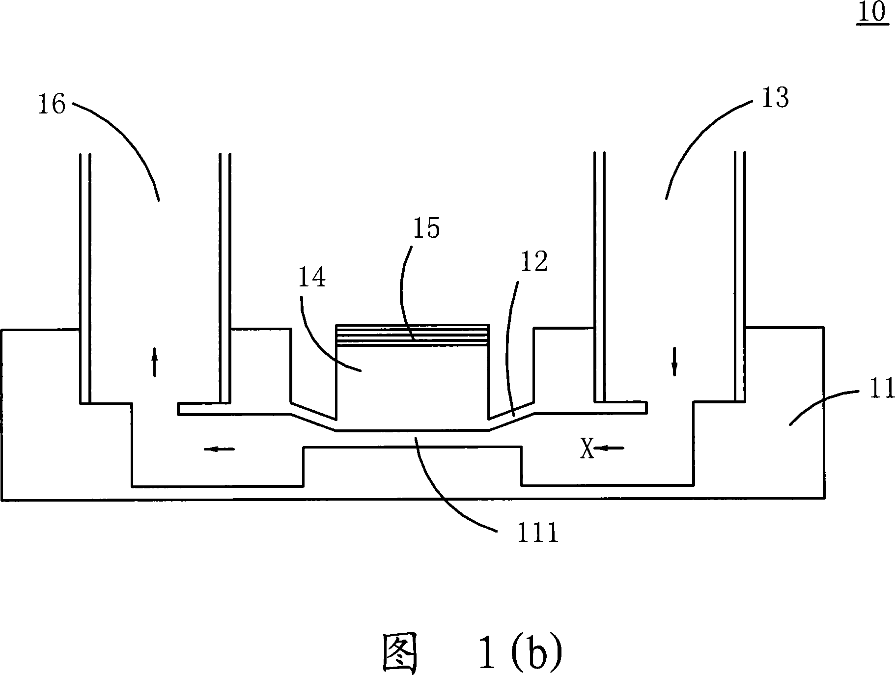
[0006] This kind of micropump structure 10 without physical valves is prone to a large amount of backflow of fluid, so in order to increase the flow rate, the compression chamber 111 needs to have a larger compression ratio , in order to generate enough chamber pressure, it needs to spend a higher cost on the actuator 15

Method used


Image

  • Fluid delivery device
  • Fluid delivery device
  • Fluid delivery device

Examples


Embodiment Construction

[0031] Some typical embodiments embodying the features and advantages of the present invention will be described in detail in the description in the following paragraphs. It should be understood that the invention is capable of various changes in different aspects without departing from the scope of the invention, and that the description and illustrations therein are illustrative in nature and not limiting. this invention.

[0032] see image 3 , which is a schematic diagram of the structure of the fluid delivery device of the present invention. As shown in the figure, the fluid delivery device 20 of the present invention can be applied to industries such as medical biotechnology, computer technology, printing or energy, and can transport gas or liquid, but Not limited to this, the fluid delivery device 20 is mainly composed of a valve body seat 21, a valve body cover 22, a valve body film 23, a plurality of temporary storage chambers, an actuator 24 and a cover body 25, whe...


PUM


Abstract

The invention relates to a fluid conveying appliance used for conveying a fluid, comprising a valve body seat, a valve body cover body, a valve body membrane, a plurality of temporary storage chambers and a rapping device, wherein, the valve body seat is provided with an outlet passage and an inlet passage; the valve body cover body is arranged on the valve body seat; the valve body membrane is arranged between the valve body seat and the valve body cover body; a first temporary storage chamber is formed between the valve body membrane and the valve body cover body, a second temporary storagechamber is formed between the valve body membrane and the valve body seat, wherein, the first temporary storage chamber and the second temporary storage chamber are respectively provided with a guidance face structure extending from an outer edge to a central direction; and the periphery of the rapping device is fixedly arranged on the valve body cover body, and a pressure cavity chamber providedwith one guidance face structure on the periphery is formed between the rapping device and the valve body cover body.

Description

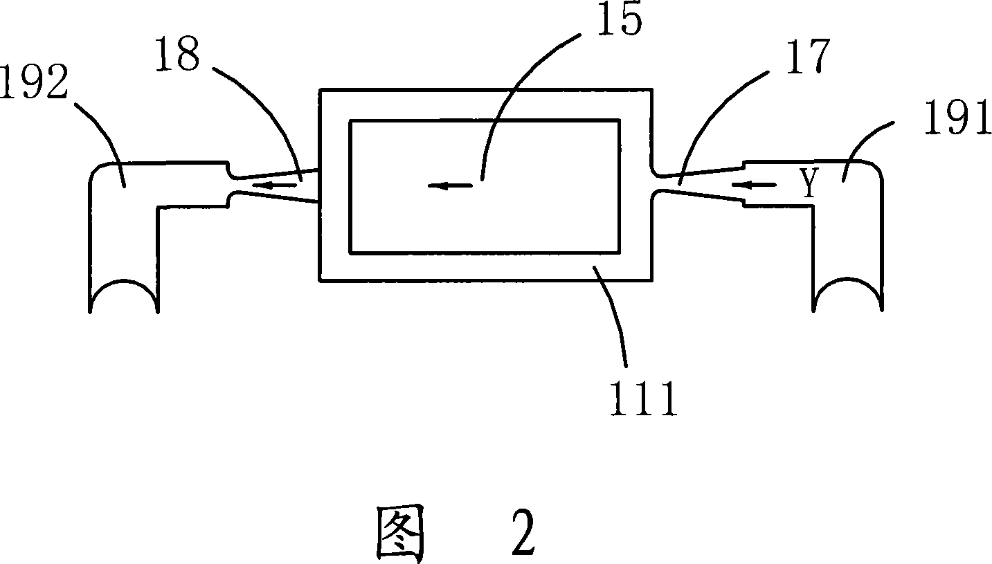
technical field [0001] The invention relates to a fluid conveying device, especially a fluid conveying device suitable for a micropump structure. Background technique [0002] At present, in various fields, whether it is medicine, computer technology, printing, energy and other industries, products are developing towards refinement and miniaturization. Among them, the fluid delivery structures included in products such as micropumps, sprayers, inkjet heads, and industrial printing devices As its key technology, how to break through its technical bottleneck with the help of innovative structure is an important content of development. [0003] Please refer to Fig. 1 (a), it is the structural representation of known micropump structure when not actuating, and known micropump structure 10 comprises inlet channel 13, microactuator 15, transmission block 14, interlayer film 12, The compression chamber 111, the base plate 11 and the outlet channel 16, wherein a compression chamber...

Claims


Application Information

Patent Timeline
Patent Type & Authority Patents(China)
IPC IPC(8): F04B43/02
CPCF04B53/1062F04B43/0009F04B43/02F04B45/04
Inventor 陈世昌张英伦余荣侯邱士哲
Owner MICROJET TECH
Learn More