
Energy-saving road lamp

A street lamp and lamp tube technology, which is applied in the field of energy-saving street lamps, can solve the problems of insufficient use of light, reduced reflectivity, and reduced street lamp brightness, and achieves the effects of improving light utilization, slow attenuation of reflectivity, and good reflection effect.

Inactive Publication Date: 2009-06-24
东莞市宝利节能有限公司
View PDF0 Cites 12 Cited by
  • Summary
  • Abstract
  • Description
  • Claims
  • Application Information

AI Technical Summary

Problems solved by technology

Among them, most of the existing reflectors are made of shiny metal (such as thin aluminum) or the surface of the reflector is coated with a chemical substance (such as chromium oxide, etc.) that reflects light, so that the upward The irradiated light is reflected and used as lighting to improve the brightness of the entire street lamp; however, the above-mentioned reflector has a low reflectivity and cannot make full use of the upwardly irradiated light, and any metal reflector, once in contact with the air for a long time, will It will be oxidized and deteriorated, the reflectivity will be reduced, and the brightness of the entire street lamp will be reduced; and the reflector coated with chemical substances will peel off due to long-term high temperature and oxidation, and lose the function of reflecting light; therefore, the current street lamp The light utilization rate is low, the power consumption is large, and the service life is not long

Method used


Image

  • Energy-saving road lamp
  • Energy-saving road lamp
  • Energy-saving road lamp

Examples


Embodiment Construction

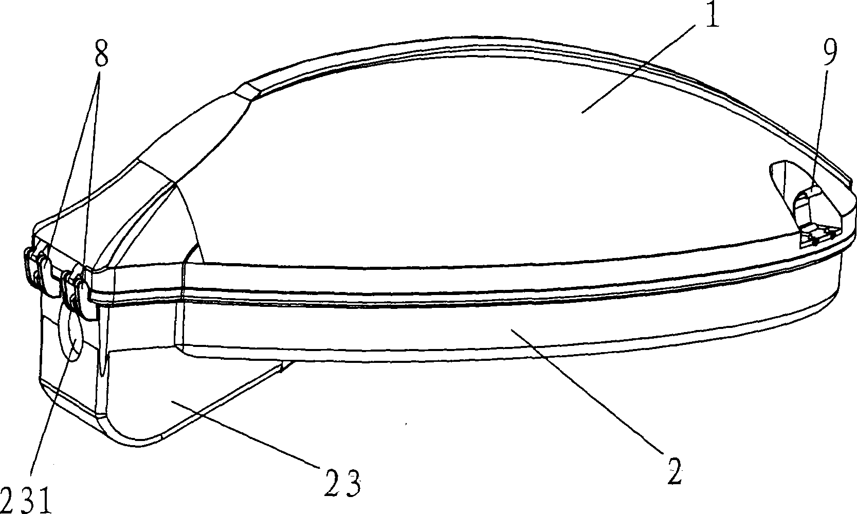
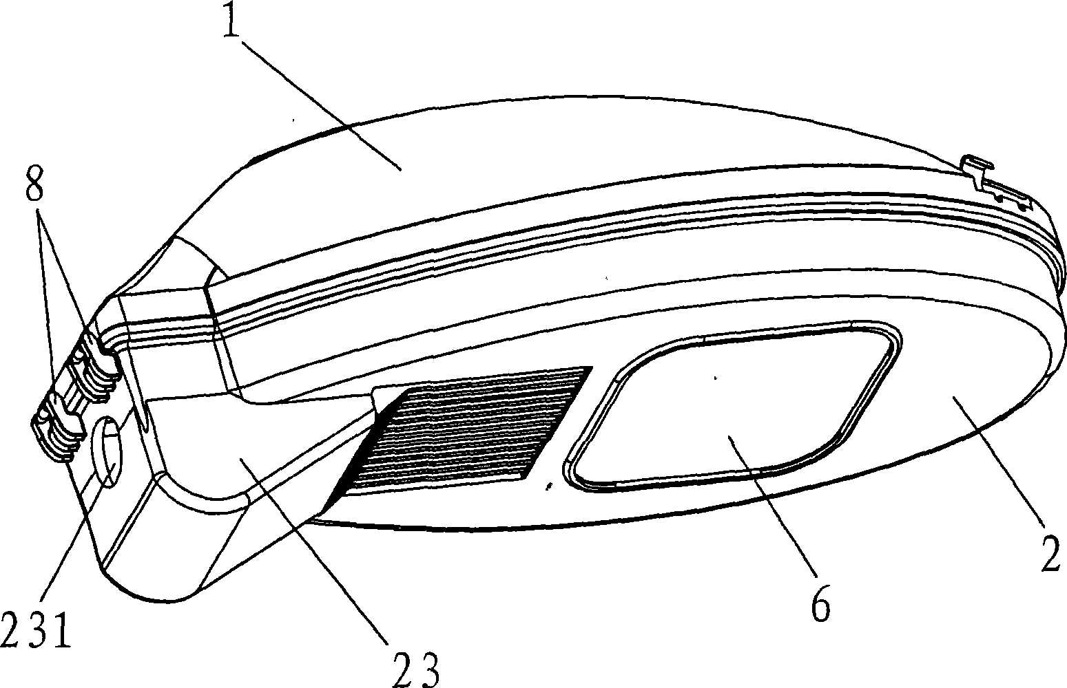
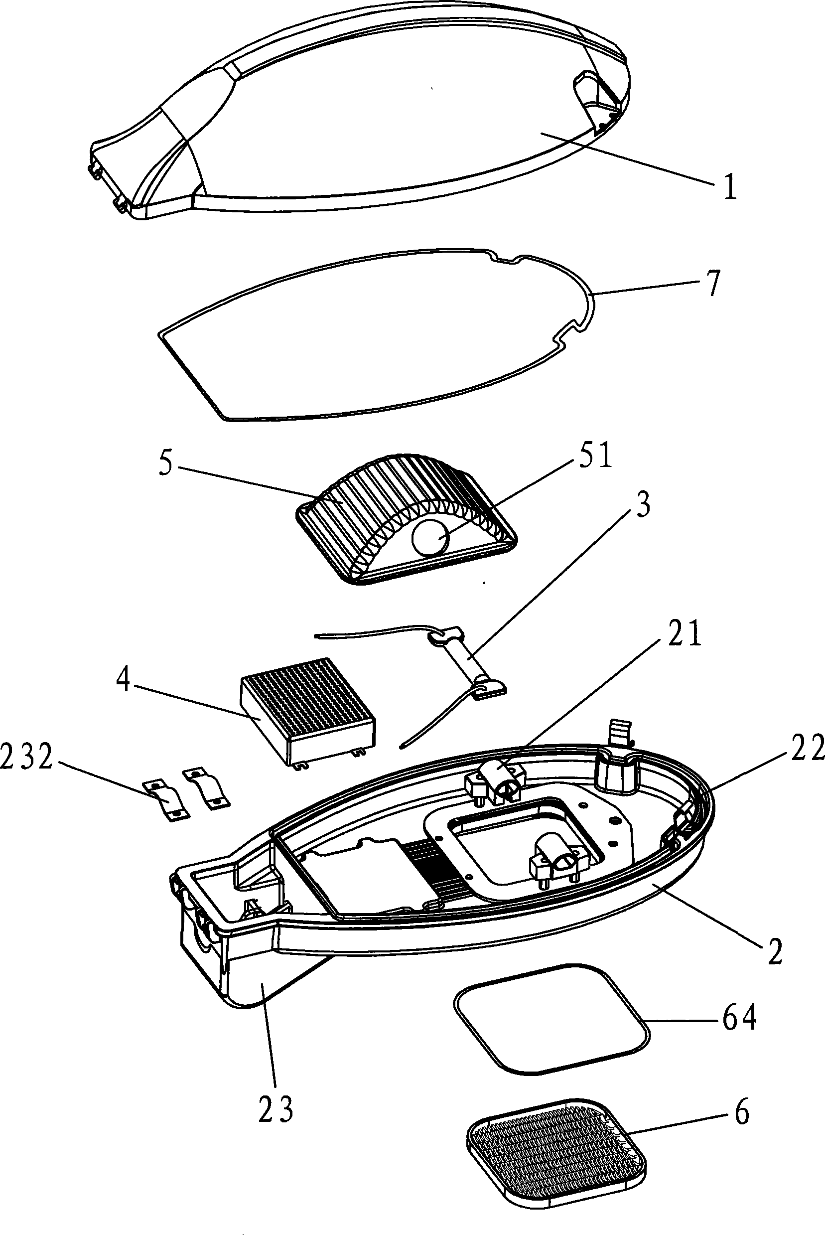
[0028] The present invention will be further explained below in conjunction with the drawings, please refer to Figure 1~10 , Is the first embodiment of the present invention, which includes an upper cover 1, a lower cover 2, a lamp tube 3, an electronic ballast 4 for providing power to the lamp tube 3, a reflector 5, the upper cover 1 and the lower cover 2 are mutually Fastened, the lamp tube 3 is located between the upper cover 1 and the lower cover 2, the reflector 5 is fixed between the lamp tube 3 and the upper cover 1, and the lower cover 2 is provided with a transparent mirror 6 corresponding to the lamp tube 3, so The reflector 5 is provided with a through hole 51 for placing the lamp tube 3; the reflector 5 is composed of an outer protective layer 52, a nano-reflective layer 53, and an inner protective layer 54. The nano-reflective layer 53 is sprayed on the outer protective layer 52. On the bottom surface, the inner protective layer 54 is sprayed on the bottom surface of ...


PUM


Abstract

The invention relates to street lamp technology field, in particular to an energy-saving street lamp, which comprises an upper cover, a lower cover, a lighting tube, an electronic ballast providing power for the lighting tube and a reflecting shade, wherein the upper cover snaps with the lower cover, the lighting tube locates between the upper cover and the lower cover, the reflecting shade is fixed between the lighting tube and the upper cover, the lower cover is equipped with a transmitting filter corresponding to the lighting tube, and the reflecting shade is equipped with a through hole for the placement of the lighting tube; the reflecting shade comprises an outer protective layer, a nanometer glistening layer and an inner protective layer, wherein the nanometer glistening layer is sprayed on the undersurface of the outer protective layer, the inner protective layer is sprayed on the undersurface of the nanometer glistening layer; as the nanometer glistening layer possesses a favorable reflection rate, namely, a higher reflection rate for visible light, and the nanometer glistening layer also possesses a favorable inoxidability, thus the weakening of the reflection rate can slow down, and the layer still possesses favorable reflection effects even though the layer services a long time, thus compared with the traditional lamp, the energy-saving street lamp of the invention consumes less electric power and possesses a longer service life.

Description

Technical field: [0001] The invention relates to the technical field of street lamps, in particular to an energy-saving street lamp. Background technique: [0002] In recent years, with global energy shortages and shortages, countries all over the world are advocating energy conservation and have invested a lot of manpower and material resources to develop new energy-saving technologies, hoping that energy use can be effectively saved. Among them, the road lighting fixtures that consume a lot of electric energy-street lamps, naturally need to apply new energy-saving technologies to meet the energy-saving concept advocated now. [0003] At present, street lamps mainly include a shell, a lamp tube arranged in the shell, an electronic ballast for supplying power to the lamp tube, and a reflector for reflecting upward light rays. The shell is provided with a transparent mirror corresponding to the lamp tube to make The light emitted by the lamp tube can be irradiated without letting ...

Claims


Application Information

Patent Timeline
Patent Type & Authority Applications(China)
IPC IPC(8): F21V7/10F21V7/22H05B41/14F21W131/103
CPCY02B20/72
Inventor 黄首仁
Owner 东莞市宝利节能有限公司
Learn More