Supercharge Your Innovation With Domain-Expert AI Agents!

LED light projecting lamp

A technology of LED lamps and lamps, applied in the direction of light source, fixed light source, point light source, etc., can solve the problems of inconvenient installation, broken glass, waste of light and electric energy, etc., to reduce waterproof and dustproof structure, improve light utilization rate, Strong and reliable structure

Inactive Publication Date: 2011-04-27
东莞市六减六光电科技有限公司
View PDF0 Cites 0 Cited by
  • Summary
  • Abstract
  • Description
  • Claims
  • Application Information

AI Technical Summary

Problems solved by technology

According to the principle that the illuminance is inversely proportional to the square of the distance, increasing the distance can only significantly reduce the illuminance of the illuminated surface, which indirectly wastes electric energy;
[0004] 2. The installation of the lamp is not reliable, and the light is easy to deviate from the normal direction
Due to technical and other reasons, the existing LED floodlights need to be composed of multiple lights or light strips to form a lighting system, and the shooting direction adjustment mechanism is easy to fail and change direction, causing individual lamps to deviate from the normal shooting direction;
[0005] 3. Poor light uniformity
The existing pear-shaped symmetrical light distribution has a large light drop, resulting in a large difference in brightness of the illuminated surface, that is, poor light uniformity, while the light intensity ratio of the reflector-type asymmetrical light distribution on the upper and lower sides is below 1.5 / 1, reaching Less than a reasonable 2.5-3 / 1, it can only be compensated by extending the distance, resulting in waste of light and electricity;
[0006] 4. Installation is inconvenient and affects the appearance of the object to be illuminated
Due to the large size of the existing LED floodlights, it is inconvenient to install and conceal, which affects the overall appearance of the illuminated object;
[0007] 5. Prone to broken glass
Due to waterproofing, hard glass is required to transmit light, and the glass is often broken for various reasons, resulting in failure of the lamp function and personal injury

Method used


Image

  • LED light projecting lamp
  • LED light projecting lamp
  • LED light projecting lamp

Examples


Embodiment Construction

[0030] In order to facilitate the understanding of those skilled in the art, the present invention will be further described in detail below in conjunction with the accompanying drawings and specific embodiments.

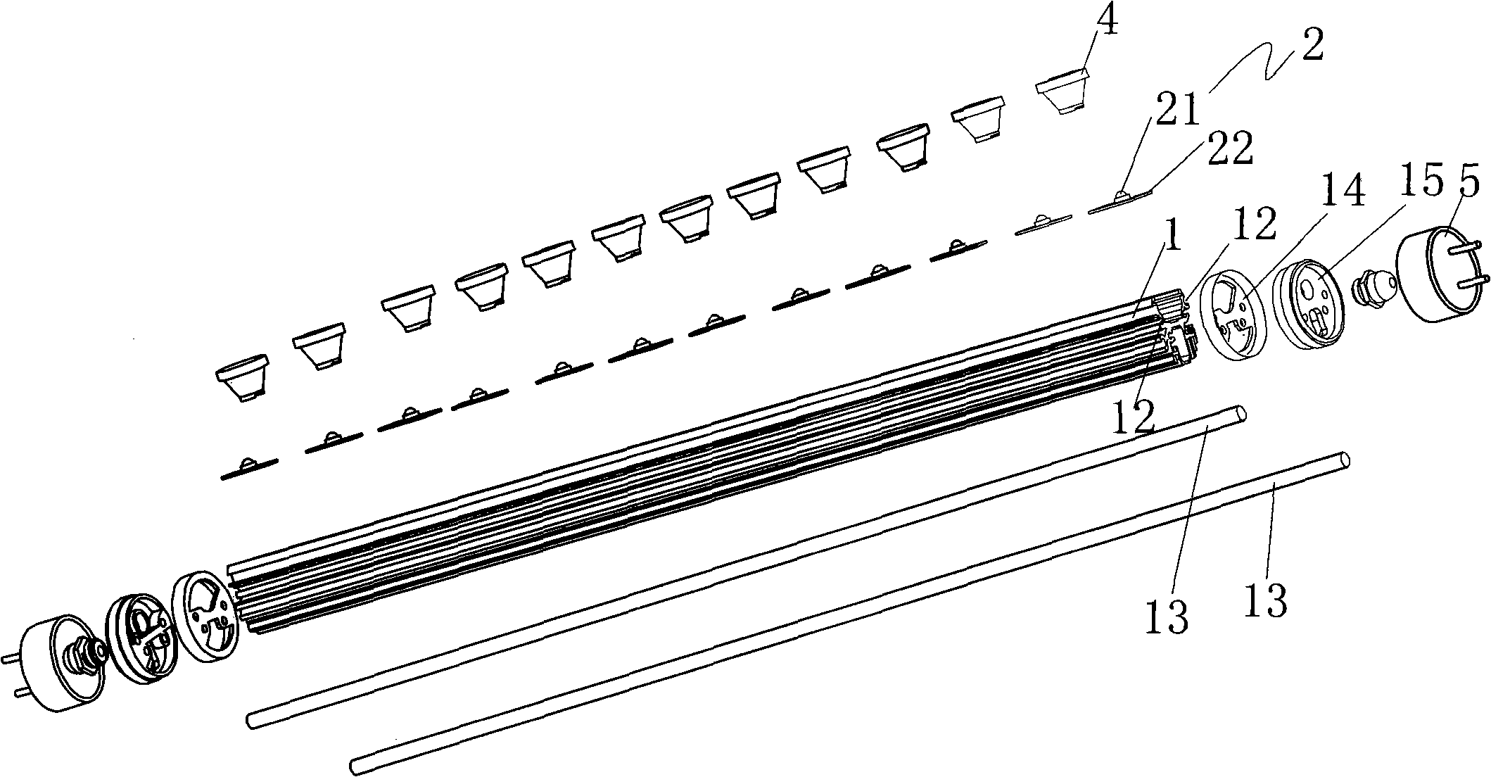
[0031] as attached Figure 1-7 As shown, the LED projection lamp disclosed in this embodiment is a projection lamp suitable for lighting such as advertisements, signboards, blackboards, and buildings. It has high light utilization rate, firm and reliable lamp structure, good integrity, and uniform light. LED floodlights with good brightness and flexible and reasonable light distribution.

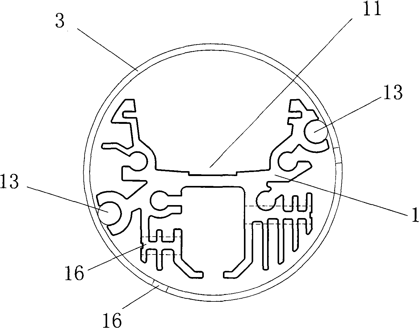
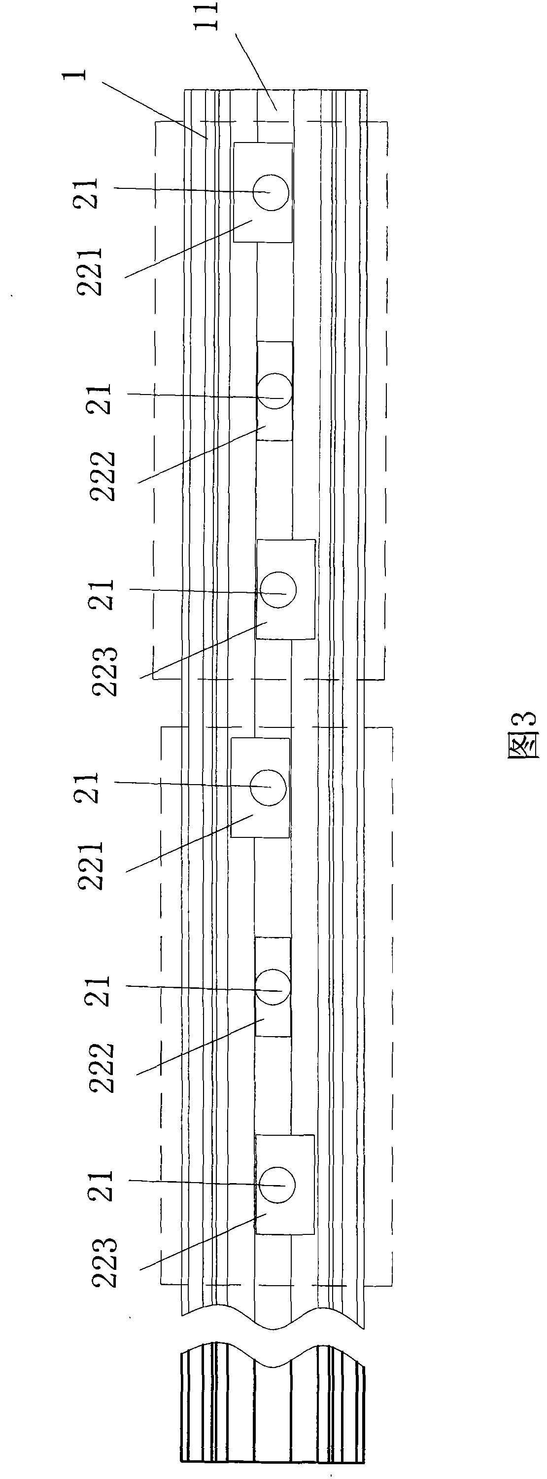
[0032] The lamp comprises a strip-shaped heat sink 1, a lampshade 3 is placed over the heat sink 1, and waterproof rubber pads 14 and waterproof plugs 15 are sequentially arranged at both ends of the heat sink 1. Groove 11, the rear light-emitting component 2 is installed in the groove 11. Wherein, the heat sink 1 is an integral aluminum part with good thermal conductivity, and ...


PUM


Abstract

The invention relates to an LED flood light, comprising a strip-shaped radiating piece, a luminescence component fixed in the radiating piece and a lampshade sheathed at the periphery of the radiating piece, the luminescence component comprises an LED light and an aluminum base plate which is used to fix the LED light, a photospot is sheathed at the front end of every LED light, the radiating piece is provided with a longitudinal groove, the LED lights are flat stuck at the bottom part of the groove and are slantingly arranged at two edges of the groove. By renovating the structure of the LEDflood light and by grouping three or more than three luminescence components which are slantingly arranged in the groove of the radiating piece, the LED flood light improves the utilization rate of light and saves electric energy, in addition, a plurality of luminescence components emit mutually overlapped and supplemented light, thus ensuring better uniformity of light.

Description

technical field [0001] The invention relates to an illuminating device, more precisely, an LED floodlight lamp. Background technique [0002] In the existing various lighting occasions such as billboards, signboards, blackboards and building night scenes, a large number of floodlights are used. With the maturity of high-power LED lamp technology, LED lamps are characterized by energy saving, environmental protection and long life. Features are increasingly favored by people. LED floodlights are also increasingly valued by people. In the existing structure of LED floodlights, LED lights are generally arranged linearly on a plane, and light-transmitting components with a single beam angle are used. LED floodlights with this structure have the following defects: [0003] 1. Low utilization rate of light. In order to make the light distribution uniform, it can only be far away from the object to be illuminated. According to the principle that the illuminance is inversely pro...

Claims


Application Information

Patent Timeline
Patent Type & Authority Patents(China)
IPC IPC(8): F21Y101/02F21V29/00F21V31/00F21V19/00F21V29/506F21V29/83F21Y115/10
CPCF21K9/17F21Y2101/02F21K9/27F21Y2115/10
Inventor 梁赖
Owner 东莞市六减六光电科技有限公司
Features
  • R&D
  • Intellectual Property
  • Life Sciences
  • Materials
  • Tech Scout
  • Unparalleled Data Quality
  • Higher Quality Content
  • 60% Fewer Hallucinations
Learn More