
Test device for turbulent flow gas-liquid blending flow field in transverse flow

A testing device and gas-liquid technology, which are applied in the field of turbulent gas-liquid mixing flow field testing devices in cross flow, can solve the problems of affecting PIV shooting and difficult shooting of flow field distribution, and achieve the effects of compact structure, easy operation and time saving.

Inactive Publication Date: 2009-06-24
XI AN JIAOTONG UNIV
View PDF0 Cites 31 Cited by
  • Summary
  • Abstract
  • Description
  • Claims
  • Application Information

AI Technical Summary

Problems solved by technology

[0005] 1. The atomization of the centrifugal nozzle will produce a liquid film on the inner wall of the channel, which will affect the PIV shooting
[0006] 2. When studying the cross-sectional flow field of jet direct spray mixing, it is generally replaced by gas, but when centrifugal nozzles are used, this method is no longer applicable
[0010] 3. The cross-sectional flow field distribution perpendicular to the cross-flow direction is difficult to photograph
[0011] 4. There are many shooting sections, and the position of the shooting system and the measurement section should be frequently adjusted and calibrated

Method used


Image

  • Test device for turbulent flow gas-liquid blending flow field in transverse flow
  • Test device for turbulent flow gas-liquid blending flow field in transverse flow
  • Test device for turbulent flow gas-liquid blending flow field in transverse flow

Examples


Embodiment Construction

[0025] Below in conjunction with example and accompanying drawing, the present invention is further described.

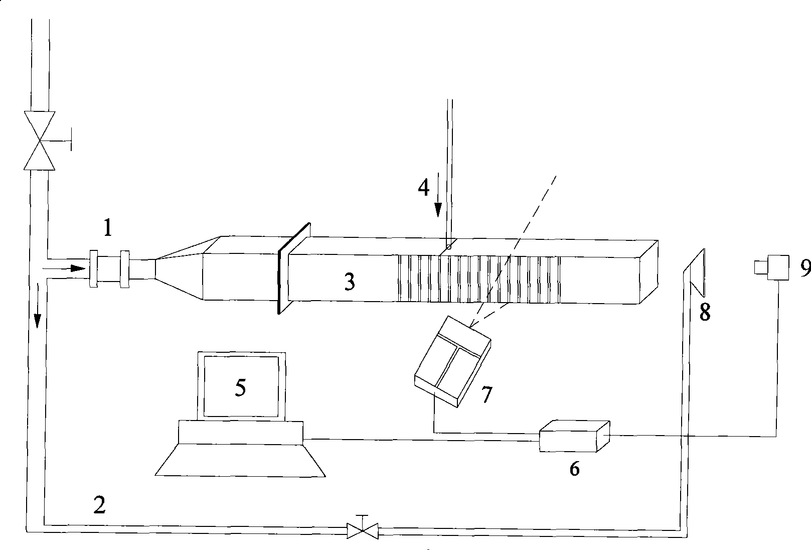
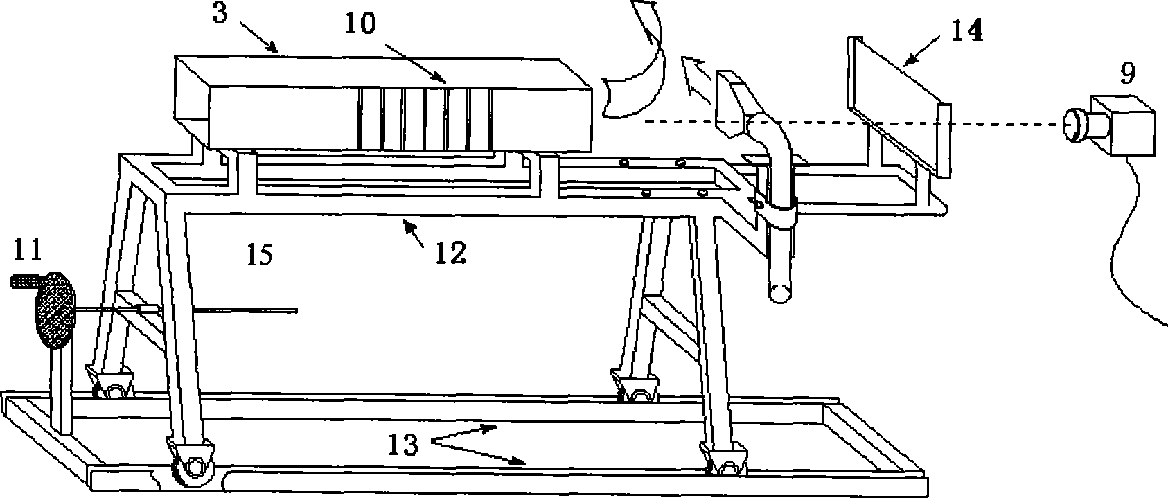
[0026] see figure 1 , 2, the present invention comprises experiment frame 12 and is arranged on experiment frame 12 and the mixing test section 3 that communicates with main air flow 1, is provided with the atomizing nozzle 4 that communicates with it on mixing test section 3, blends The inner wall of the test section 3 is uniformly coated with matte paint, and several slits 10 are opened on the side wall of the mixing test section 3, and a double pulse Nd: YAG laser 7, CCD camera 9 is arranged at the exit of mixing test section 3, said double-pulse Nd: YAG laser 7 and CCD camera 9 are respectively connected with computer 5 through PIV (Particle Image Velocimetry) synchronous controller 6. On the main air flow 1, also be connected with side air flow 2, the side air path outlet 8 of this side flow 2 is fixed on the test frame 12 and is positioned at the outlet of bl...


PUM


Abstract

A device for testing a turbulent flow blending flow field in a crosscurrent comprises a blending test section communicated with a main airflow; an atomizing nozzle is arranged on the blending test section and communicated therewith; matt paint is uniformly applied onto the inner wall of the blending test section; a plurality of slits are formed on the lateral wall of the blending test section; a double pulse Nd:YAG laser is arranged on one side of the blending test section, and the slits are formed on the side; a CCD camera is arranged at the outlet of the blending test section; and the double pulse Nd:YAG laser and the CCD camera are connected with a computer through a PIV synchronous controller separately. The invention addresses the difficulties in filming the flow field of a rotating flow centrifugal nozzle in a limited passage during the process of atomizing blending in the cross flow, such as liquid accumulation on the inner wall, the influence of ambient light, the arrangement of the camera and frequent calibration due to the filming of different sections, and at last can obtain a clear blending particle picture, thereby obtaining the important information about the flow field, the velocity field, the distribution of vorticity and the like.

Description

technical field [0001] The invention belongs to a flow field testing device, in particular to a turbulent gas-liquid mixing flow field testing device in a cross flow capable of obtaining a swirling centrifugal nozzle spray mixing flow field in a cross section perpendicular to the main flow direction. Background technique [0002] Water atomization is widely used in various industrial applications, such as steam turbines, industrial dust removal, nuclear reactor depressurization and cooling, atomization humidification, furnace cooling, spray mixing in water ramjet engines, propulsion devices for liquid propellant artillery, etc. The quality of water-air two-phase mixing is one of the most important aspects. Due to the large water output of the straight jet flow and the low pressure required, the nozzles in these fields mostly use jet nozzles. So far, the vast majority of research has also focused on jet nozzles and cross-flow mixing. The research content includes jet (water)...

Claims


Application Information

Patent Timeline
IPC IPC(8): G01M10/00
Inventor 白博峰张海滨刘利孙慧娟
Owner XI AN JIAOTONG UNIV
Learn More