
Method for orientating secondary pixel edge of oval-shaped target

A sub-pixel edge and positioning method technology, applied in image analysis, image data processing, instruments, etc., can solve time-consuming problems

Inactive Publication Date: 2009-06-24
HAIAN COUNTY SHENLING ELECTRICAL APPLIANCE MFG +1
View PDF0 Cites 31 Cited by
  • Summary
  • Abstract
  • Description
  • Claims
  • Application Information

AI Technical Summary

Problems solved by technology

For all the above moment-based methods, since multiple templates are used to convolve the image, the algorithm is time-consuming

Method used


Image

  • Method for orientating secondary pixel edge of oval-shaped target
  • Method for orientating secondary pixel edge of oval-shaped target
  • Method for orientating secondary pixel edge of oval-shaped target

Examples


Embodiment 1

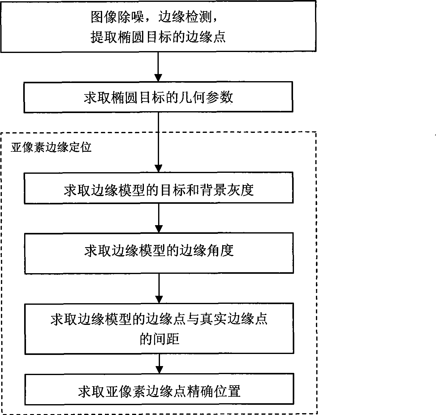
[0063] The specific embodiments of the present invention will be further described below in conjunction with the accompanying drawings. Applying this method to locate the sub-pixel edge of an ellipse object mainly includes three steps: detecting the pixel-level edge of the ellipse object, calculating the geometric parameters of the ellipse, and locating the sub-pixel edge. The flow chart of the specific steps is as follows: image 3 As shown, the specific steps for applying this method to locate the sub-pixel edge of an ellipse target are as follows:

[0064] Step 1: Denoise the image, perform Sobel operator edge detection, then extract the edge points of the ellipse object, record the total number of edge points count_pixel, and store the coordinates of the pixel-level edge points, expressed as (x p ,y p ), p=1, 2, 3...count_pixel, wherein, the pixel-level edge point indicates that the coordinates of the edge point are at the integer pixel level;

[0065] Step 2: Use the ed...

Embodiment 2

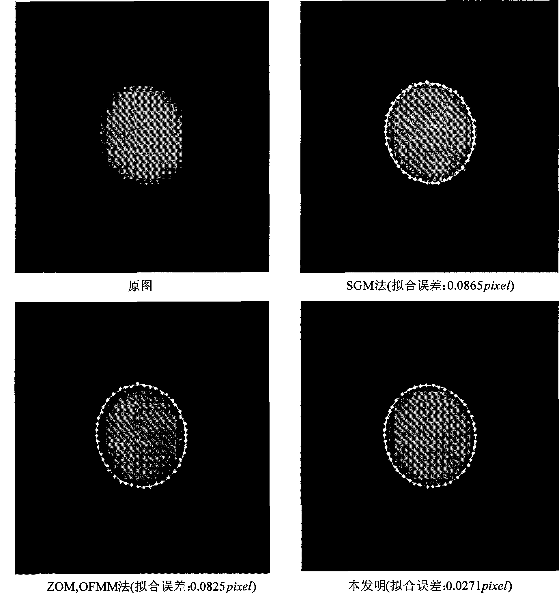
[0115] According to above-mentioned method, adopt the present invention to such as Figure 7 The actual image shown contains an elliptical target for sub-pixel edge location, the specific process is as follows:

[0116] Step 1: Denoise the image, detect the edge of the Sobel operator, and then extract the edge points of the ellipse object. The extracted ellipse edge points are as follows Figure 8 As shown, record the total count_pixel of edge points, at this time, count_pixel=47; store the coordinates of pixel-level edge points, expressed as (x p ,y p ), p=1, 2, 3...count_pixel, wherein, the pixel-level edge point indicates that the coordinates of the edge point are an integer pixel level, and the stored pixel-level edge point coordinates are shown in Table 6;

[0117] Step 2: Use the edge points of the ellipse target extracted in the first step, and use the method of least squares to fit the edge points to obtain the general equation x of the ellipse 2 +A e xy+B e the y...


PUM


Abstract

A sub-pixel edge of an ellipse target positioning method mainly relates to a image processing and machine vision such as calculation of accurate parameters and calibration and matching of a pick-up camera of the ellipse target and the like, the method is mainly divided into three main steps: the first step includes noise elimination of images, edge detection by Sobel operators and extraction of edge points of the ellipse target; the second step includes calculation of geometric parameters of the ellipse target; and the third step includes position of the sub-pixel edge, wherein, the position of the sub-pixel edge can be divided into four parts of calculating target grayness and background grayness of the edge model, calculating edge angles, calculating the distance between edge points and real edge points and calculating accurate position of sub-pixel edge points. The sub-pixel edge of positioning method comprehensively utilizes geometric parameters of the ellipse target, distribution characteristics of grayness of the ellipse target and two-dimensional edge models. The method not only effectively improves the accuracy and the robustness of the edge positioning, but also greatly reduces arithmetic quantity so as to enhance the rapidity.

Description

technical field [0001] The invention relates to a sub-pixel edge positioning method of an ellipse target, in particular to a moment-based sub-pixel edge positioning method of an ellipse target. Background technique [0002] Edge is the most basic feature of an image, and quickly and accurately locating edges plays an important role in image processing and computer vision. A circle is a common figure, which is transformed into an ellipse through perspective projection transformation. Accurately obtaining the edge of an ellipse target is an important issue in optical measurement at present. At present, the image edge detection technology has reached the sub-pixel level, and the common sub-pixel edge location methods can be divided into three categories: fitting method, interpolation method, and moment-based method. The literature "High-accuracyedge detection with Blurred Edge Model" (Ye J, Fu G K, Poudel U P. Image and Vision Computing, 2005, 23(5): 453-467) is a fitting meth...

Claims


Application Information

Patent Timeline
IPC IPC(8): G06T7/00
Inventor 达飞鹏张虎
Owner HAIAN COUNTY SHENLING ELECTRICAL APPLIANCE MFG
Learn More