Photocatalysis oxidation water purification tank

A photocatalytic oxidation and purification tank technology, which is applied in the direction of oxidized water/sewage treatment, special compound water treatment, light water/sewage treatment, etc., can solve the problems of high treatment cost, small treatment capacity, unsafety, etc., and achieve improvement Effects of removal rate, reduction of treatment cost, and improvement of utilization efficiency

Inactive Publication Date: 2009-07-01
BEIJING JINAOHUARONG TECH
View PDF0 Cites 12 Cited by
  • Summary
  • Abstract
  • Description
  • Claims
  • Application Information

AI Technical Summary

Problems solved by technology

[0002] Photocatalytic oxidation is a water treatment technology with a deep purification degree, which can oxidize most organic pollutants, such as alkanes, fatty alcohols, fatty acids, olefins, phenols, organic acids, aromatics, dyes, polychlorinated biphenyls, surface Various pollutants such as active agents and pesticides require a high degree of water purification. For water sources subject to a certain degree of organic pollution, only relying on filtration treatment or aerobic biochemical treatment, the organic pollutants in it still cannot reach For the deep purification treatment in this case, people often use membrane filtration and other methods for treatment. Since the treatment volume of these treatment methods is relatively small and the treatment cost is relatively high, they are subject to large-scale water treatment. certain restrictions
[0003] On the other hand, the problem of low-concentration organic pollution in water is becoming more and more prominent, such as trace natural organic substances and various toxic and harmful synthetic organic substances in drinking water sources, disinfection by-products in drinking water, and possible Traces of endocrine disruptors and persistent organic compounds, some trace organic pollutants are also unsafe in wastewater reuse

Method used


Image

  • Photocatalysis oxidation water purification tank

Examples


Embodiment Construction

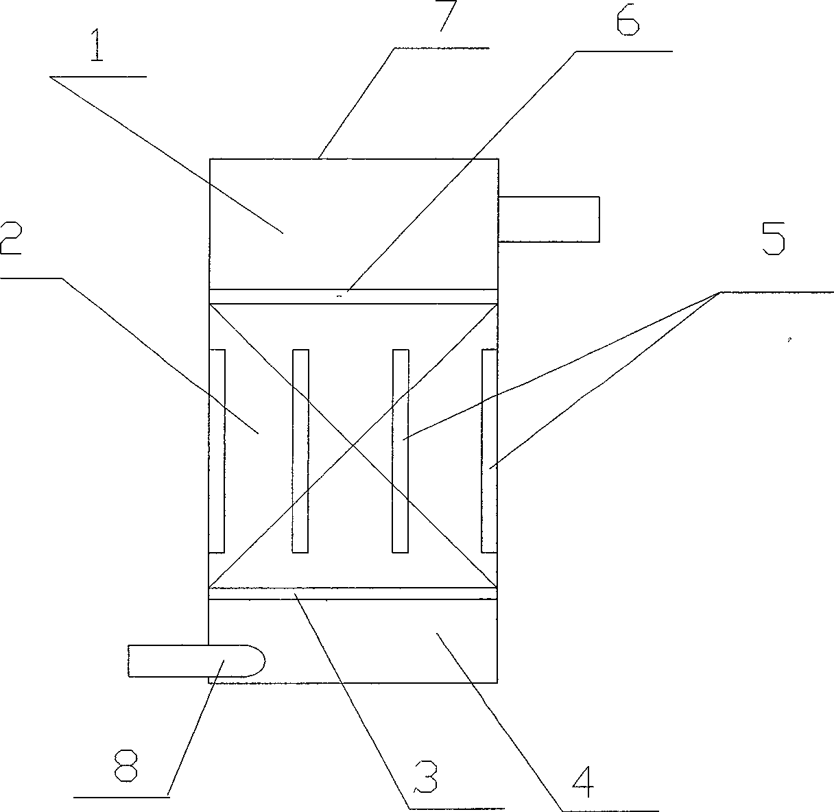
[0010] see figure 1 , the present invention provides a photocatalytic oxidation purification tank, which is provided with two upper and lower horizontal partitions 6, 3 to divide the inner space of the tank into a middle part, an upper part and a lower part, and the upper and lower partitions are all orifice plates, wherein the upper The plate is a small-hole orifice plate, and the lower partition is a large-hole orifice plate. The middle part of the inner space of the tank is a fluidized bed chamber 2, the lower part is a mixing chamber 4, and the upper part is a steady flow chamber 1. The fluidized bed chamber is set There are some ultraviolet light lamps 5 extending vertically, and photocatalyst particles 9 are housed inside. The surface of the photocatalyst particles is covered with photocatalysts. The water inlet pipe 8 of the purification tank is connected with the mixing chamber, and its extension direction is along the Oblique or tangential, the outlet pipe of the puri...


PUM


Abstract

The invention relates to a photocatalytic oxidation and purification tank. The photocatalytic oxidation and purification tank is provided with an upper transverse clapboard and a lower transverse clapboard to divide a space of the tank into a middle part, an upper part and a lower part; the upper clapboard and the lower clapboard are orifice plates, wherein the upper clapboard is a small orifice plate; the lower clapboard is a large orifice plate; the middle part of the space in a tank body is a fluidized bed chamber; the lower part is a mixed chamber; the upper part is a steady flow chamber; the fluidized bed treatment chamber is provided with a plurality of ultraviolet lamps; the inside of each ultraviolet lamp is filled with photocatalyst particles; the surfaces of the photocatalyst particles are distributed with photocatalyst; a water inlet pipe of the purification tank is connected with the mixing chamber; the extending direction of the water inlet pipe is oblique or tangential; a water outlet pipe of the purification tank is connected with the steady flow chamber; the extending direction of the water outlet pipe is radial; and the tank body is also provided with an ozone inlet pipe which can be independently mounted or can adopt the same pipe with the water inlet pipe. The device has high purification degree, relatively large treatment amount and relatively lower treatment cost and is mainly suitable for occasion with higher requirement on purification degree of outlet water.

Description

technical field [0001] The invention relates to a water purification treatment device with photocatalytic oxidation as the main purification method, which is mainly suitable for occasions where the purification degree of effluent water is required to be high. Background technique [0002] Photocatalytic oxidation is a water treatment technology with a deep purification degree, which can oxidize most organic pollutants, such as alkanes, fatty alcohols, fatty acids, olefins, phenols, organic acids, aromatics, dyes, polychlorinated biphenyls, surface Various pollutants such as active agents and pesticides require a high degree of water purification. For water sources subject to a certain degree of organic pollution, only relying on filtration treatment or aerobic biochemical treatment, the organic pollutants in it still cannot reach For the deep purification treatment in this case, people often use membrane filtration and other methods for treatment. Since the treatment volume ...

Claims


Application Information

Patent Timeline
Patent Type & Authority Applications(China)
IPC IPC(8): C02F1/78C02F1/32
CPCC02F2101/322C02F2101/306C02F1/006C02F2101/308C02F2305/10C02F2101/325C02F1/325C02F1/78
Inventor 董玉波
Owner BEIJING JINAOHUARONG TECH
Why Eureka
Try Eureka