Camshaft and crankshaft position correlation simulation methods and systems

A technology of crankshaft position and simulation system, applied in the field of diagnosis system, can solve the problem of time-consuming and expensive disassembly and reassembly of the engine, etc.

Inactive Publication Date: 2009-07-01
GM GLOBAL TECH OPERATIONS LLC
View PDF0 Cites 14 Cited by
  • Summary
  • Abstract
  • Description
  • Claims
  • Application Information

AI Technical Summary

Problems solved by technology

This method of disassembling and reassembling the engine is time consuming and expensive

Method used


Image

  • Camshaft and crankshaft position correlation simulation methods and systems
  • Camshaft and crankshaft position correlation simulation methods and systems
  • Camshaft and crankshaft position correlation simulation methods and systems

Examples


Embodiment Construction

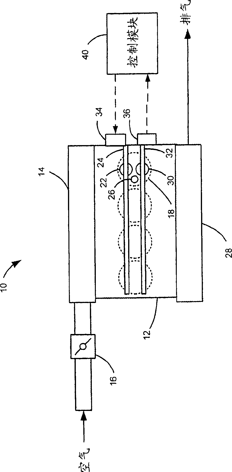
[0012] The ensuing description is merely exemplary in nature and is not intended to limit the invention, its application or uses. It should be understood that throughout the drawings, corresponding reference numerals indicate like or corresponding parts and features. As used herein, the term "module" refers to an application-specific integrated circuit (ASIC), an electronic circuit, processor (shared, dedicated, or group) and memory, combinational logic circuit, that executes one or more software or firmware programs, and / or other suitable components capable of providing the described functionality.

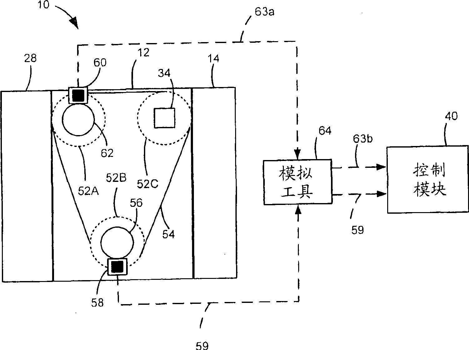
[0013] now refer to figure 1 An engine system 10 includes an engine 12 that combusts an air and fuel mixture to produce drive torque. Air is drawn into an intake manifold 14 through a throttle valve 16 . Throttle valve 16 regulates air flow into intake manifold 14 . Air within the intake manifold 14 is distributed to the cylinders 18 . Although only four cylinders 18 are ill...


PUM


Abstract

The invention relates to a camshaft and crankshaft position relevance analogy method and a system, which is aimed at providing a system designed for simulating an internal combustion engine when incorrect valve timing exists. The analogy system is aimed at calibrating and/or verifying a special camshaft-crankshaft relevance diagnosis algorithm. The analogy system comprises an analogy module which is communicated with a crankshaft position sensor, a camshaft position sensor and a motor control module; wherein the analogy module comprises a first selector selected for processing the lapse value of a periodic signal, and a correction module for receiving the camshaft position signal from the camshaft position sensor and generating corrected camshaft position signal based on the crankshaft position signal and the lapse value.

Description

technical field [0001] The invention relates to a diagnostic system for an internal combustion engine. Background technique [0002] The statements in this section merely provide background information related to the present invention and may not constitute prior art. [0003] Internal combustion engines may include one or more intake and / or exhaust camshafts for adjusting intake and / or exhaust valve timing. The camshaft position sensor produces a camshaft position signal that indicates the position of the camshaft. The control module monitors the camshaft position signal to determine engine position. The control module performs diagnostics to ensure that the engine position is reliable. [0004] During a diagnosis, a technician disassembles the engine and reinstalls the camshaft to advance or retard the camshaft relative to the crankshaft. Then, the diagnostics are tested to verify correct operation. For example, the diagnostics should be able to diagnose whether the r...

Claims


Application Information

Patent Timeline
Patent Type & Authority Applications(China)
IPC IPC(8): F01L1/344F02D41/00
CPCF01L2800/11F01L1/02
Inventor M·D·格雷S·F·哈勒
Owner GM GLOBAL TECH OPERATIONS LLC
Why Eureka
Try Eureka