Fan and stator holder thereof

A fixed seat and fan technology, which is applied to the components of pumping devices for elastic fluids, non-variable-capacity pumps, pump devices, etc., can solve the problems of large noise, large vibration, shortening the service life of fans, etc. Damage to the structure, good joint effect, effect of increasing the strength of the base

Inactive Publication Date: 2009-07-01
DELTA ELECTRONICS INC
View PDF0 Cites 4 Cited by
  • Summary
  • Abstract
  • Description
  • Claims
  • Application Information

AI Technical Summary

Problems solved by technology

[0003] In the background technology, metal bearing sleeves and metal bases are usually designed for high-precision integration with the connected devices. Therefore, if the design of the device is changed, the metal bearing sleeves and metal bases also need to be changed. Even the metal bearing sleeves and

Method used


Image

  • Fan and stator holder thereof
  • Fan and stator holder thereof
  • Fan and stator holder thereof

Examples


Embodiment Construction

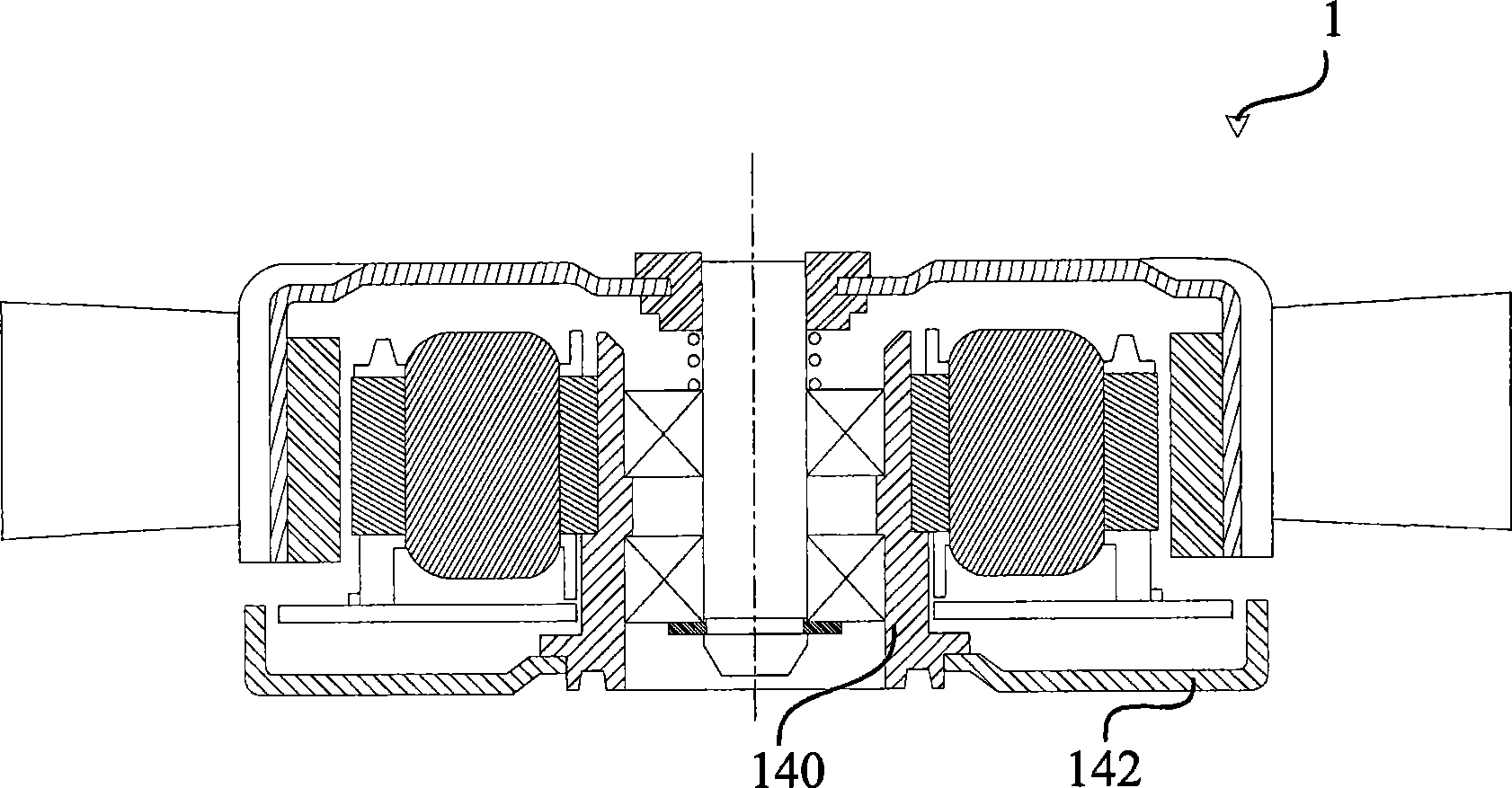
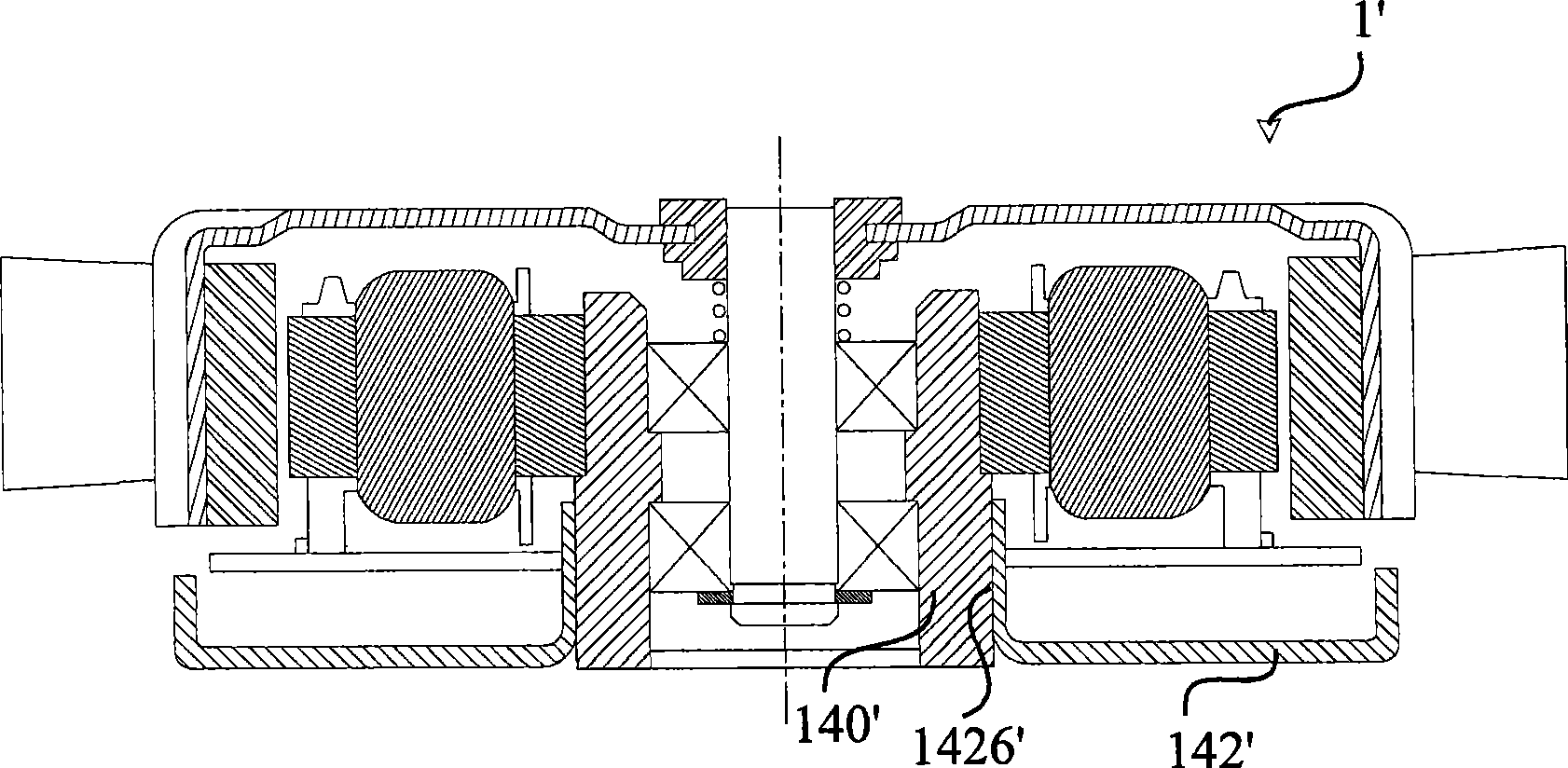
[0026] see Figure 2A , which is a sectional view of the fan 2 according to the first preferred embodiment of the present invention. The fan 2 includes an impeller 20 , a stator structure 22 , a stator fixing seat 24 and a bearing 26 . The stator structure 22 is arranged corresponding to the impeller 20 . The stator fixing seat 24 is used for supporting the stator structure 22 . The stator structure 22 includes an electromagnetic element 220 such as a coil and a driving circuit board 222 . The stator fixing seat 24 includes a plastic bearing sleeve 240 , a metal base 242 and an anti-vibration medium 244 . The bearing 26 is located between the stator fixing seat 24 and the rotating shaft 200 of the impeller 20 . In addition, the stator fixing seat 24 can be connected with devices 9 such as fan frame or system frame.

[0027] The metal base 242 has a connecting portion 2420 and a fixing portion 2422 . The connecting portion 2420 is engaged with the plastic bearing sleeve 2...


PUM


Abstract

The present invention discloses a fan stator permanent seat which is used to bear a stator structure of a fan, wherein the fan stator permanent seat includes a plastic rubber bearing sleeve and a metal base plate. The metal base plate is provided with a interconnecting piece which is covered by the plastic rubber bearing sleeve.

Description

technical field [0001] The invention relates to a stator fixing seat, and in particular to a fan and its stator fixing seat. Background technique [0002] see Figure 1A to Figure 1C , which respectively show the cross-sectional views of the existing fans 1, 1' and 1". Figure 1A As shown, the metal base 142 of the fan 1 is connected to the bottom of the metal bearing sleeve 140, which is fixed by riveting. Such as Figure 1B As shown, the metal base 142' of the fan 1' is connected with the metal bearing sleeve 140' through a bearing hole 1426' having the same height, which is fixed by coupling. Such as Figure 1C As shown, the bearing seat 18" of the fan 1" is made of metal bearing sleeve and metal base by aluminum die-casting. Therefore, the bearing seat 18" has the functions of supporting the bearing 16" and fixing the device at the same time. [0003] In the background technology, the metal bearing sleeve and the metal base are usually designed in a high-precision i...

Claims


Application Information

Patent Timeline
IPC IPC(8): F04D25/08F04D29/05
Inventor 林政锽邱永裕
Owner DELTA ELECTRONICS INC
Why Eureka
Try Eureka