
Detection system and method for mesomeric state hydrogen gas consumption

A detection system and consumption technology, applied in the direction of weighing, electrical components, measuring devices, etc., can solve the problems of additional readings, inaccurate measurement, etc., and achieve the effect of improving accuracy and convenient research

Inactive Publication Date: 2009-07-01
TSINGHUA UNIV
View PDF0 Cites 22 Cited by
  • Summary
  • Abstract
  • Description
  • Claims
  • Application Information

AI Technical Summary

Problems solved by technology

When measuring by gravimetric method, the section of pipeline connected to the gas cylinder will generate stress. For high-precision electronic balances, such force can easily cause additional readings, resulting in inaccurate measurement

Method used

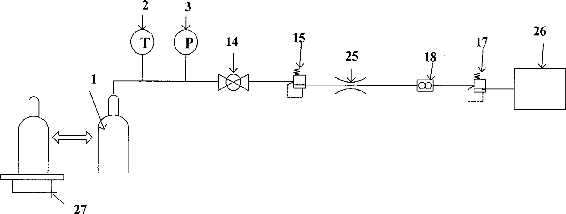
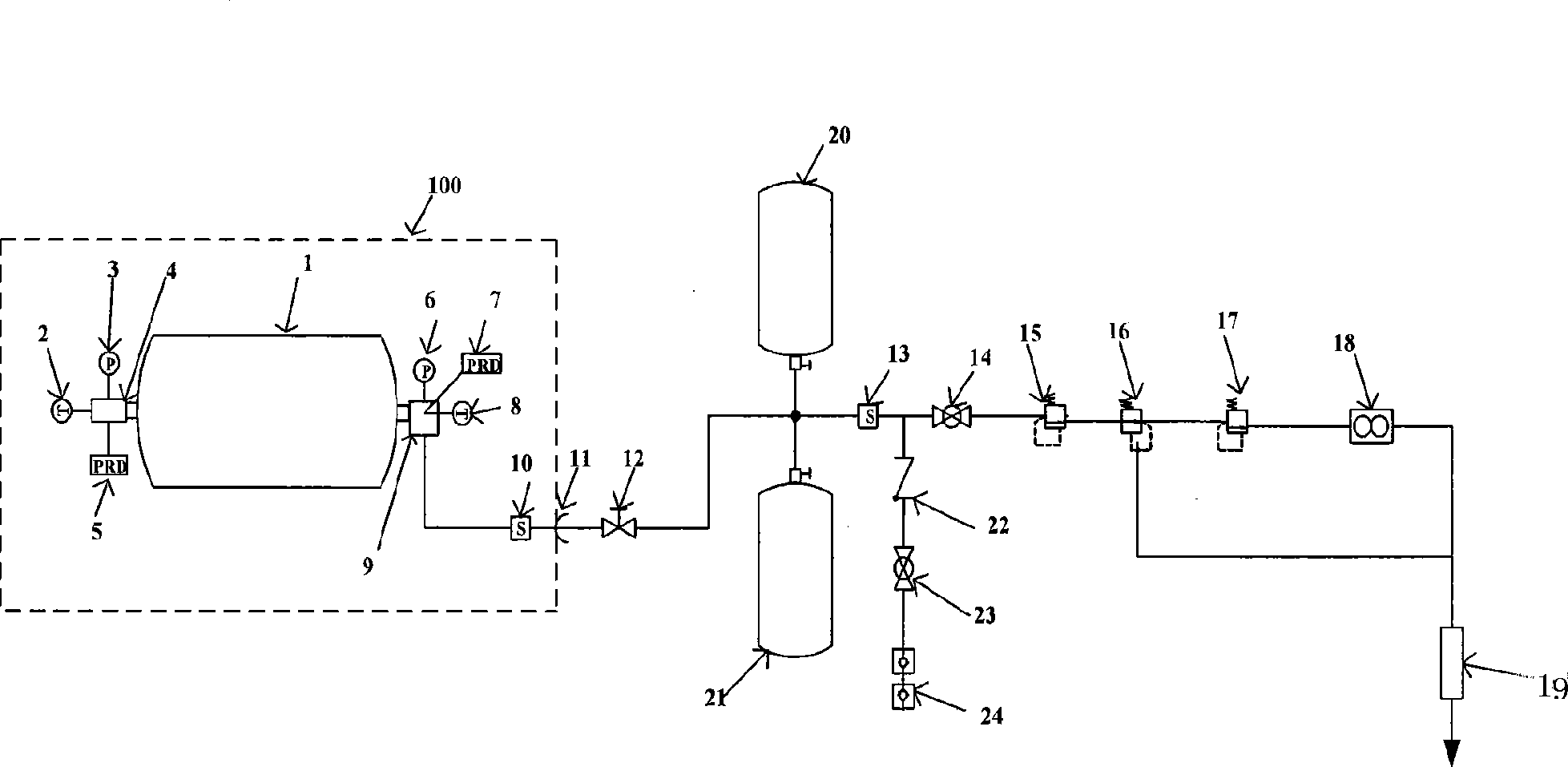
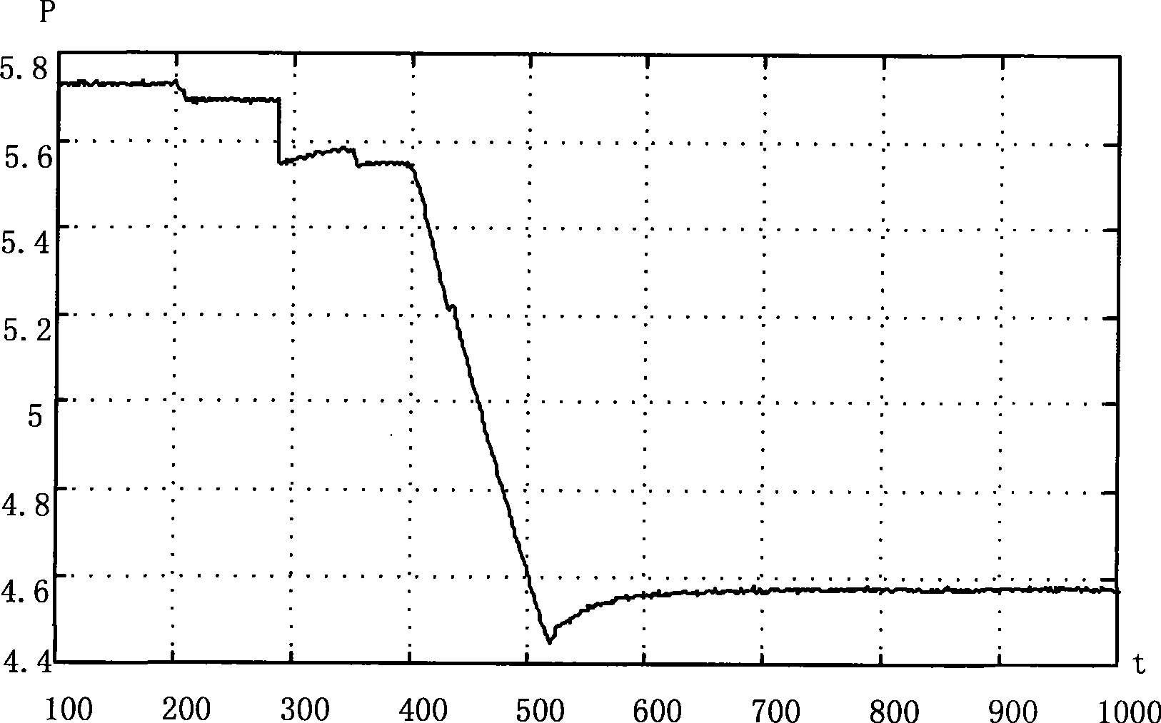

Image

  • Detection system and method for mesomeric state hydrogen gas consumption
  • Detection system and method for mesomeric state hydrogen gas consumption
  • Detection system and method for mesomeric state hydrogen gas consumption

Examples


Embodiment 1

[0057] refer to figure 2 , a steady-state hydrogen consumption detection system, the main line connected with the bottle valve 9 of the high-pressure gas cylinder 1 is sequentially installed with a bottle mouth solenoid valve 10, a ferrule-type joint 11, a detachable pipeline screw valve 12, and a main line Solenoid valve 13, dry manual valve 14, first stage pressure reducing valve 15, safety valve 16, second stage pressure reducing valve 17, flow controller 18 and flame arrester 19; detachable pipeline screw valve 12 and dry circuit Two branch pipelines of hydrogen cylinder 21 and nitrogen cylinder 20 for purging are installed on both sides of the main pipeline between solenoid valves 13; A branch pipeline of a one-way valve 22, a filling pipeline manual valve 23 and a filling interface 24 connected in sequence is installed on the side.

[0058] The cylinder valve 9 of the high-pressure gas cylinder 1 is integrated with a cylinder valve pressure sensor 6, a cylinder valve t...

Embodiment 2

[0071] Such as figure 2 , before connecting the weighing area 100 composed of the high-pressure gas cylinder 1 with hydrogen and the bottle mouth solenoid valve 10 into the hydrogen consumption detection system, first use the electronic balance to weigh the weighing area 100 three times, and record the electronic balance respectively. The three readings are taken and the average value is obtained, and the mass of the weighing area 100 before deflation is 31183.7 grams. After deflation ends and waits for 30 minutes, turn off the power, disassemble the weighing area 100 from the ferrule, and unplug the electrical connection of the sensor on the weighing area 100, and use the electronic balance to weigh it again. The indication of the watch is 31091.6 grams, and the difference between the front and rear indications is 92.1 grams. The weighing area 100 is not removed from the electronic balance, and at the same time, a 50-gram weight, a 20-gram weight, a 20-gram weight and a 3-g...


PUM


Abstract

The invention relates to a steady hydrogen gas consumption detection system and a detection method thereof, belonging to the gas detection technical field. In the system, the main pipeline connected with the bottle valve of a high pressure bottle is mounted with a bottle mouth electromagnetic valve, a ferrule type joint, a detachable pipeline swirling valve, a primary road electromagnetic valve, a primary road manual valve, a first stage decompression valve, a safety valve, a second decompression valve, a flux controller and a flame arrester in turn. The method measures the weights before and after discharging the gas of the gas bottle, the temperatures and the pressures at the tail block of the gas bottle and the bottle valve, to obtain three hydrogen gas consumption value groups. The invention arranges a hydrogen bottle, a hydrogen gas bottle purging pipeline and a temperature pressure sensor in the bottle to improve measurement accuracy, comprises a filling pipeline to simply and directly fill gas into the high pressure gas bottle, and utilizes weighting method and counter weight calibration as reference, thus being convenient for the research on steady hydrogen gas consumption detection.

Description

technical field [0001] The invention belongs to the technical field of gas detection, and in particular relates to a steady-state hydrogen consumption detection system and a detection method. Background technique [0002] The power source commonly used in urban fuel cell buses is proton exchange membrane fuel cells, and the fuel source is hydrogen. A proton exchange membrane fuel cell is a device that converts hydrogen and oxidants into electrical energy and reaction products. Hydrogen enters the anode of the fuel cell through the diffusion layer, and filtered air enters the cathode through the diffusion layer. Through the action of the anode catalyst, the hydrogen atom is decomposed into two hydrogen protons (proton) and two electrons (electron), and the anode reaction is: H2→2H++2e, in which the proton is "attracted" by oxygen to the sulfonic acid type proton exchange On the other side of the membrane, electrons pass through an external circuit to form a current and then...

Claims


Application Information

Patent Timeline
IPC IPC(8): G01G17/04H01M8/04H01M8/04746
CPCY02E60/50
Inventor 卢青春聂圣芳金振华刘文斌白东方彭媛媛
Owner TSINGHUA UNIV
Learn More