Object position detection method
A detection method and object technology, applied in special data processing applications, instruments, electrical digital data processing, etc., can solve the problems of text damage, inability to correct, and engineers unable to correctly interpret text content, etc., to improve quality, shorten detection time, Improve the effectiveness of manual detection methods
- Summary
- Abstract
- Description
- Claims
- Application Information
AI Technical Summary
Problems solved by technology
Method used
Image
Examples
no. 1 example
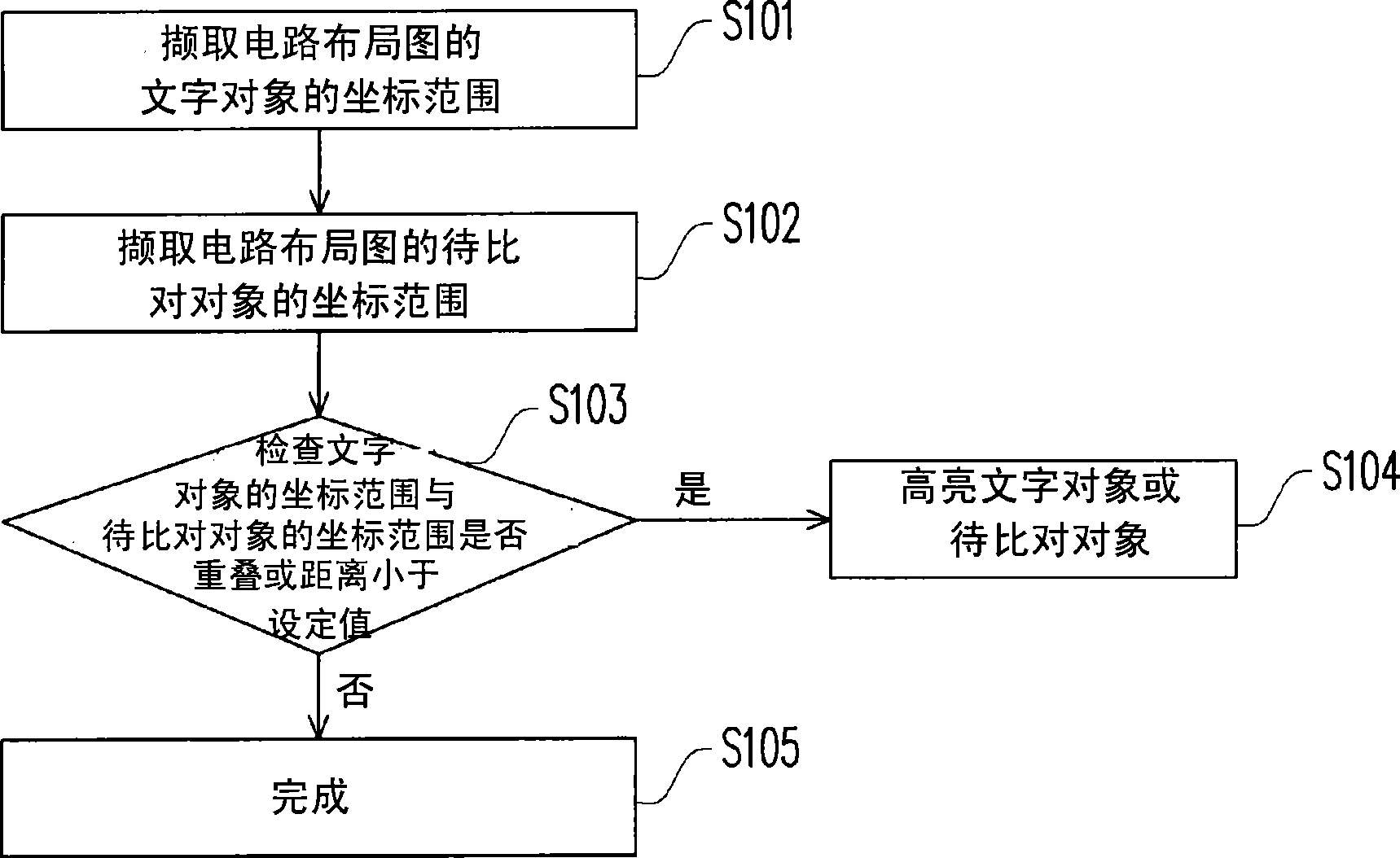
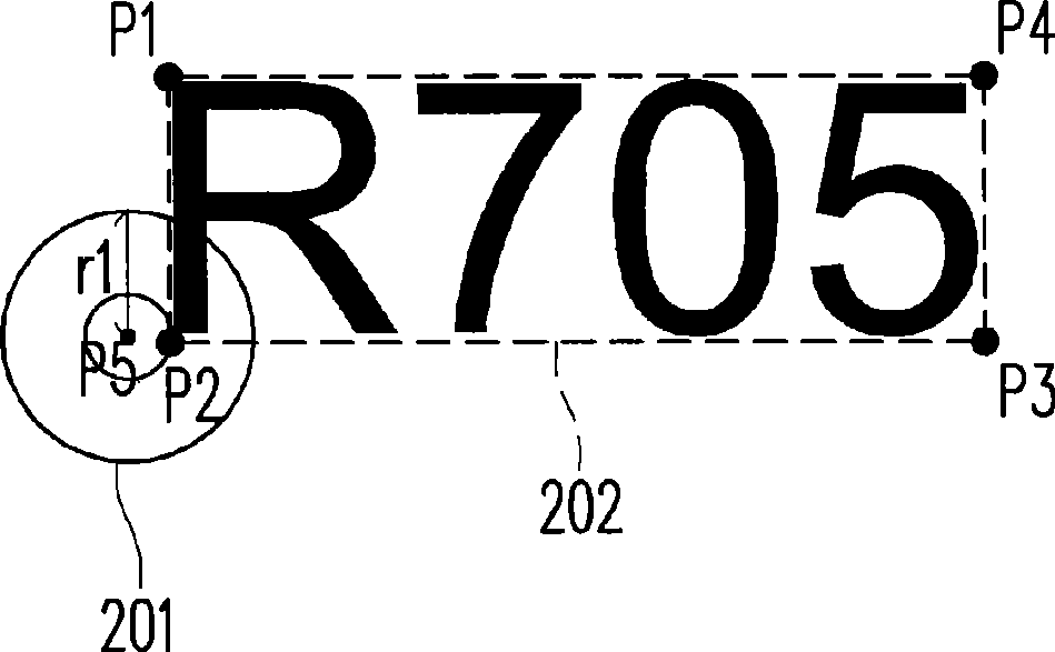
[0032] figure 1 It is a flow chart of a method for detecting an object position according to an embodiment of the present invention. figure 2 is a schematic diagram of a partial circuit layout drawn according to the first embodiment of the present invention. Please merge reference figure 1 and figure 2 , in this embodiment, the object to be compared is described by taking the through hole 201 as an example, and it is assumed that the through hole 201 overlaps with the text object 202 . Because the layout engineer is designing the circuit layout, the information of each object in the circuit layout drawing, such as the coordinate information of each object, will be recorded in the circuit layout drawing file. Therefore, in this embodiment, the object information of the circuit layout file can be extracted, so as to automatically detect the position of each object.
[0033] Firstly, the coordinate range of the text object 202 of the circuit layout diagram can be retrieved ...
no. 2 example
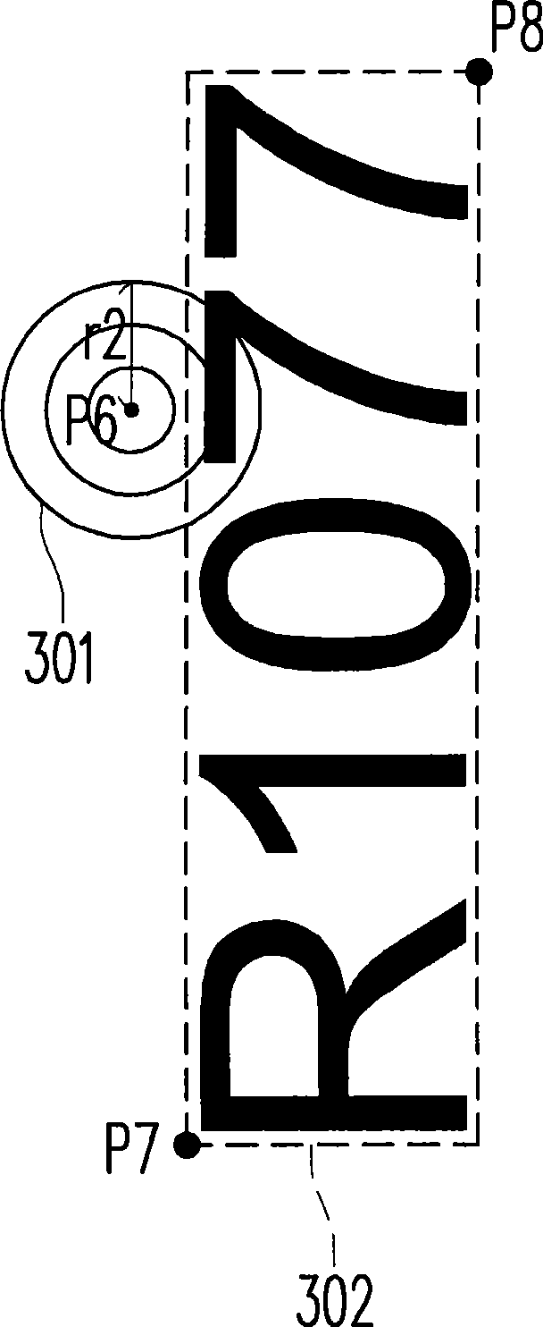
[0038] image 3 is a schematic diagram of a partial circuit layout drawn according to the second embodiment of the present invention. Please merge reference figure 1 and image 3 , in this embodiment, the object to be compared is described by taking a test point (Test Point) 301 as an example, and it is assumed that the test point 301 overlaps with the text object 302 .
[0039] Firstly, the coordinate range of the text object 302 of the circuit layout diagram can be retrieved by step S101. Those skilled in the art should know that the text object 302 is generally a rectangle, so in this embodiment, the two diagonal endpoints P7 and P8 of the text object 302 can be used to infer the four boundaries of the text object 302, and then define the text The coordinate range of the object 302.
[0040] Next, in step S102, the coordinate range of the test point 301 in the circuit layout diagram can be retrieved. In this embodiment, the coordinate range of the test point 301 can be...
no. 3 example
[0043] Those skilled in the art should know that in the above-mentioned embodiments, although the objects to be compared are described by taking through holes and test points as examples, the present invention is not limited thereto. In other embodiments, the object to be compared may also be a pad or a component. for example, Figure 4 is a schematic diagram of a partial circuit layout drawn according to the third embodiment of the present invention. Please merge reference figure 1 and Figure 4 , in this embodiment, the objects to be compared are described by taking the welding pads 401, 402 and the placement position 403 of the parts as examples, and it is assumed that the placement position 403 of the parts overlaps with the text object 404, wherein the above parts can be, for example, Source device (ActiveDevice) or passive device (Passive Device). Then, the effects similar to those of the above-mentioned embodiment can also be achieved through steps S101-S104, wherei...
PUM
 Abstract
Description
Claims
Application Information
 - R&D
- Intellectual Property
- Life Sciences
- Materials
- Tech Scout
- Unparalleled Data Quality
- Higher Quality Content
- 60% Fewer Hallucinations
Browse by: Latest US Patents, China's latest patents, Technical Efficacy Thesaurus, Application Domain, Technology Topic, Popular Technical Reports.
© 2025 PatSnap. All rights reserved.Legal|Privacy policy|Modern Slavery Act Transparency Statement|Sitemap|About US| Contact US: help@patsnap.com


