
Bearing temperature-monitoring device and bearing device with the same

A bearing temperature and monitoring device technology, which is applied to parts of thermometers, rotating bearings, bearings, etc., can solve the problems of reduced bearing load capacity, damage to the rotating shaft, and increased compression, so as to prevent deformation and excessive rise. High, the effect of improving reliability

Active Publication Date: 2009-07-01
MITSUBISHI POWER LTD
View PDF1 Cites 12 Cited by
  • Summary
  • Abstract
  • Description
  • Claims
  • Application Information

AI Technical Summary

Problems solved by technology

[0009] Moreover, in Figure 9 In the technology of Patent Document 1 shown, the metal part 03d for temperature measurement is set so that its front end surface is the same as the inner surface of the bearing member 02, and it is fixed to the bearing member 02 for installation. Therefore, due to the bearing load The amount of compression caused by the bearing part 02 made of resin material becomes larger, such as Figure 9 As indicated by the protrusion amount B shown by the dotted line, the metal piece 03d for temperature measurement protrudes relatively from the surface of the bearing member 02 to the side of the rotating shaft, protruding, causing damage to the rotating shaft, lowering the load capacity of the bearing, and, may also cause the damage to cause damage to the rotating shaft

Method used


Image

  • Bearing temperature-monitoring device and bearing device with the same
  • Bearing temperature-monitoring device and bearing device with the same
  • Bearing temperature-monitoring device and bearing device with the same

Examples


Embodiment 1

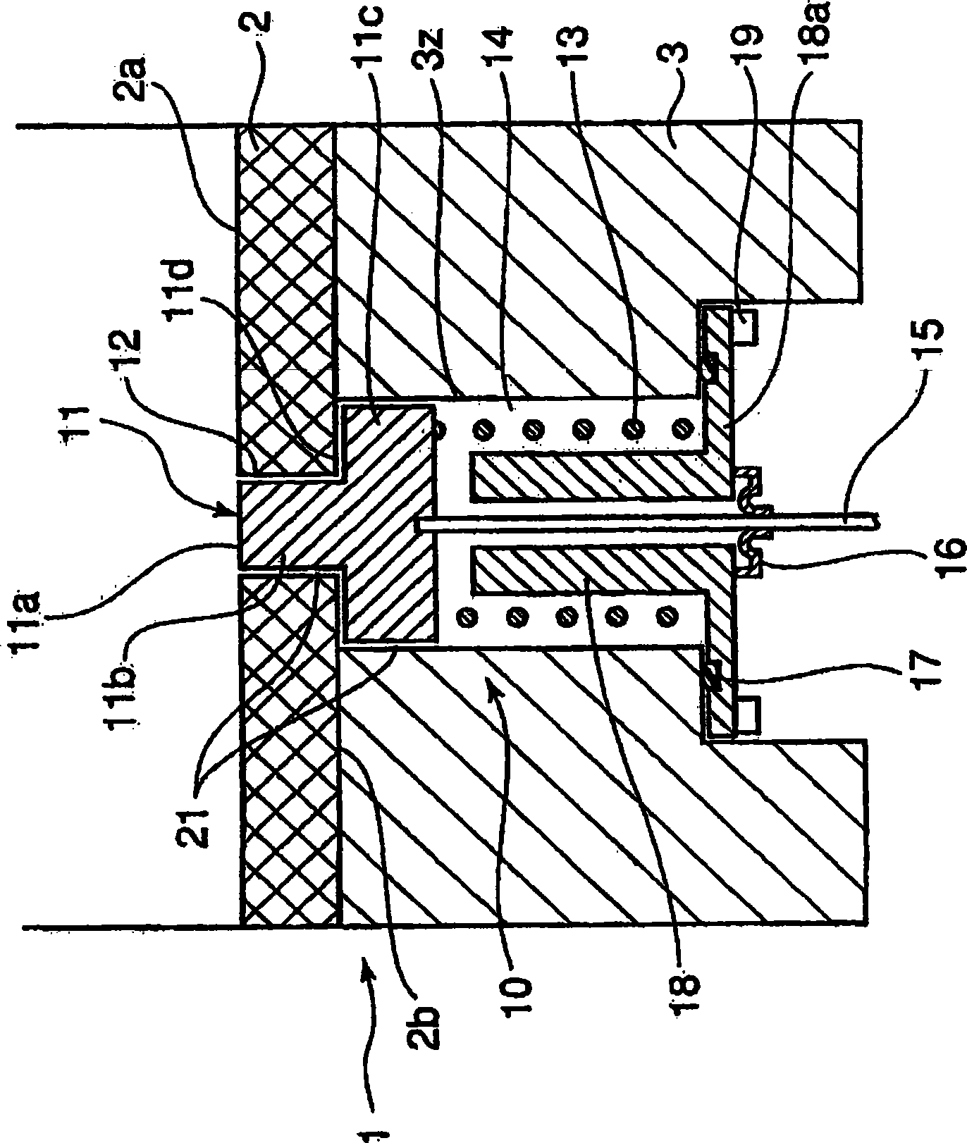
[0052] figure 1 It is a cross-sectional view of main parts along the axis line of the bearing temperature detection device of the bearing temperature monitoring device in the radial journal bearing according to the first embodiment of the present invention ( Figure 8 A-A line profile).

[0053] exist Figure 4 Among them, 3 is a metal backing made of steel, and 2 is a bearing member made of a resin material fixed inside the backing metal 3 . 12 is the installation hole of the front end portion 11b of the temperature sensing part 11 described later punched in such a way as to communicate with the inner surface 2a and the outer surface 2b of the bearing member 2, and 3z is the installation hole that communicates with the inner surface of the lining metal part 3. Mounting holes for the protruding amount limiting portion 11c of the temperature sensing member 11, the spring 13, etc., which are punched in the form of the surface and the outer surface will be described later.

...

Embodiment 2

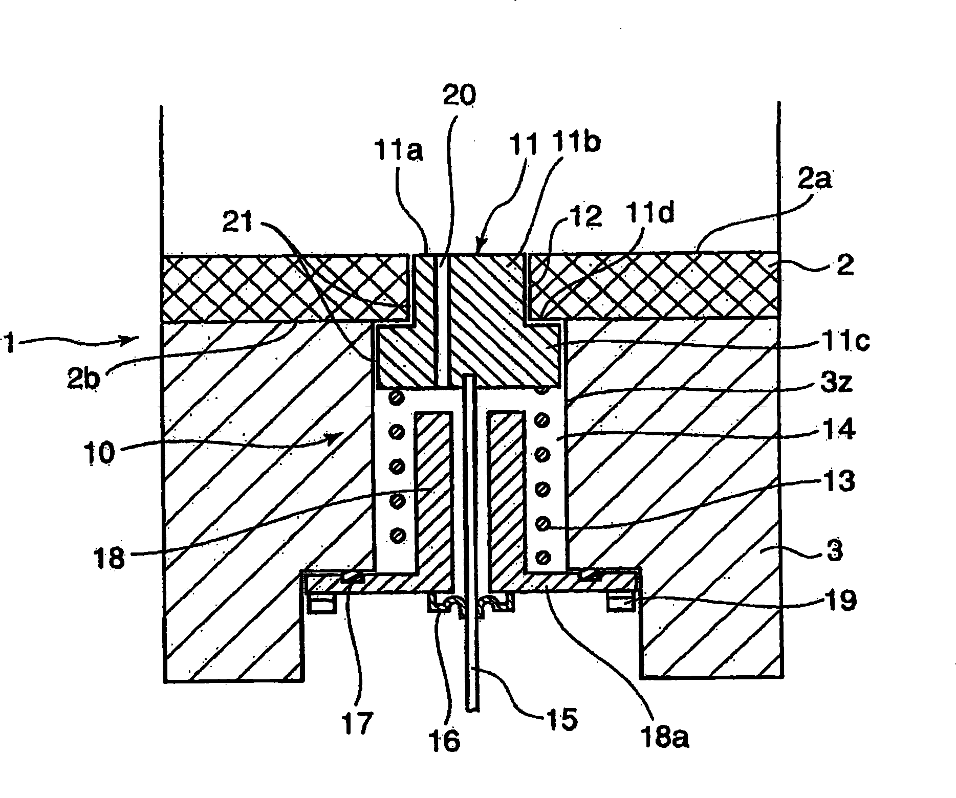
[0067] figure 2 is to represent the second embodiment of the present invention figure 1 Corresponding figure.

[0068] In the second embodiment, the temperature sensing part 11 is punched with a communication hole 20 for pressure balance that communicates the temperature detection end surface 11 a and the spring chamber 14 .

[0069] Other structures are the same as those of the first embodiment, and the same components are denoted by the same symbols.

[0070] According to the second embodiment, it can be seen that the oil on the inner surface 2a of the bearing member 2 can be easily guided to the back side of the temperature sensing member 11 through the communication hole 20, and the surface and back of the temperature sensing member 11 can be well maintained. The pressure is balanced, therefore, the gap between the temperature sensing part 11 and the bearing part 2 and the lining metal part 3 is easily adjusted without being affected by the oil film pressure of the bea...

Embodiment 3

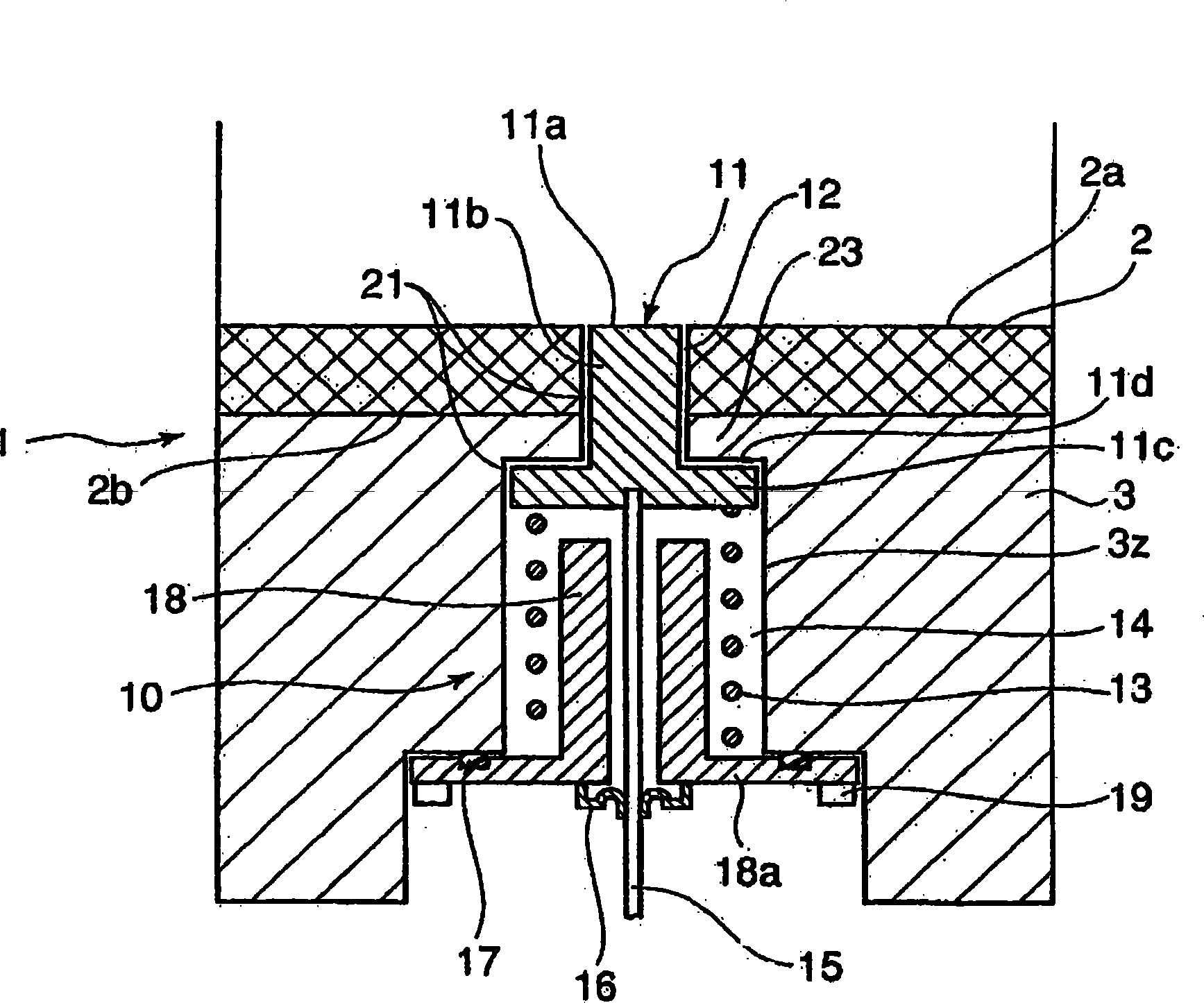
[0072] image 3 is a representation of the third embodiment of the present invention figure 1 Corresponding figure.

[0073] In this third embodiment, a protruding portion 23 is formed at the end portion of the lining metal member 3 on the side of the bearing member 2, and the protrusion amount limiting portion 11c of the temperature sensing member 11 is set by the mounting load of the spring 13 By abutting against the protruding portion 23 , the amount of protrusion of the temperature sensing member 11 toward the inner surface 2 a side of the bearing member 2 is restricted.

[0074] Other structures are the same as those of the first embodiment, and the same components are denoted by the same symbols.

[0075] According to the third embodiment, the temperature sensing member 11 is made to abut against the protruding portion 23 formed at the end portion of the backing metal fitting 3 on the bearing member 2 side. Supported by the lining metal member 3, the support rigidity...


PUM


Abstract

A bearing temperature-monitoring device and a bearing device with the bearing temperature-monitoring device. In the bearing temperature-monitoring device, occurrence of flaws on a rotating shaft caused by contact between the shaft and a metal temperature-sensing member facing the surface of a bearing member is prevented.This prevents a reduction in bearing-load carrying ability caused by the flaws and also prevents damage on the rotating shaft induced by the flaws. As a result, reliability of the bearing temperature-monitoring device is enhanced. The bearing member has an installation hole bored in the bearing member so as to penetrate to its inner surface; the temperature-sensing member relatively movably fitted in the installation hole to cause a temperature detection end surface to face a bearing surface of the bearing member, having a projection amount-limiting section for limiting the amount of projection of the temperature-sensing member to the bearing surface side, and formed from a material having a higher heat conduction rate than the bearing member; a pressing member for pressing the temperature-sensing member to the bearing member side such that the temperature-sensing member is movable by a specific amount from a projection amount limitation position to the side opposite the bearing surface; and a temperature detector electrically connected to the temperature-sensing member and detecting the temperature of the temperature-sensing member.

Description

technical field [0001] The present invention relates to a bearing temperature monitoring device for monitoring the temperature of a bearing in which a bearing member made of a resin material is fixed inside a lining metal member, and a bearing device provided with the bearing temperature monitoring device. Background technique [0002] In the radial journal bearings or thrust bearings of high-speed rotating shafts such as steam turbines and gas turbines, the inner side of the lining metal parts (the inner side refers to the shaft end surface side or the inner circumference of the sliding parts facing the inside of the machine) Surface side) A bearing with a bearing component made of resin material fixed. The resin material bearing of the high-speed rotating shaft has a large temperature rise caused by the high-speed rotation of the shaft, and the thermal conductivity of the resin material is lower than that of copper alloy bearings such as white metal. Therefore, it is requ...

Claims


Application Information

Patent Timeline
Patent Type & Authority Applications(China)
IPC IPC(8): G01K1/14F16C17/04F16C17/24G01K13/08
CPCG01K13/08F16C17/24F16C17/243
Inventor 贝漕高明山下一彦中野隆胁勇一朗上里元久山田丰
Owner MITSUBISHI POWER LTD
Learn More